Question: A capped cast-iron pipe is compressed
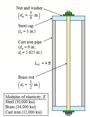
A capped cast-iron pipe is compressed by a brass rod, as shown. The nut is turned until it is just snug, then add an additional quarter turn to pre-compress the cast-iron pipe. The pitch of the threads of the bolt is p = 52 mils (a mil is one-thousandth of an inch). Use the numerical properties provided.
(a) What stresses σp and σr will be produced in the cast-iron pipe and brass rod, respectively, by the additional quarter turn of the nut?
(b) Find the bearing stress σb beneath the washer and the shear stress τc in the steel cap.
Transcribed Image Text:
Nut and washer (4. - im) 3 Steel cap (t. = 1 in.) Cast iron pipe (d, = 6 in., d; = 5.625 in.) Lei = 4 ft Brass rod (4 - m) Modulus of elasticity, E: Steel (30,000 ksi) Brass (14,000 ksi) Cast iron (12,000 ksi)
> Three prismatic bars, two of material A and one of material B, transmit a tensile load P (see figure). The two outer bars (material A) are identical. The cross-sectional area of the middle bar (material B) is 50% larger than the cross-sectional area of o
> A solid circular steel cylinder S is encased in a hollow circular aluminum tube A. The cylinder and tube are compressed between the rigid plates of a testing machine which applies forces P. Calculate the allowable value of the compressive force if the yi
> A horizontal rigid bar ABC is pinned at end A and supported by two cables at points B and C. A vertical load P = 10 kN acts at end C of the bar. The two cables are made of steel with a modulus elasticity E = 200 GPa and have the same cross- sectional are
> A steel bar with a uniform cross section is fixed at both ends. A load P = 2.5 kips is applied at point C. The bar has a cross-sectional area of 8 in2. Calculate the reactions at joints A and B and the displacement at joint C. Assume that the modulus of
> A cylindrical assembly consisting of a brass core and an aluminum collar is compressed by a load P (see figure). The length of the aluminum collar and brass core is 350 mm, the diameter of the core is 25 mm, and the outside diameter of the collar is 40 m
> A plain concrete wall (i.e., a wall with no steel reinforcement) rests on a secure foundation and serves as a small dam on a creek (see figure). The height of the wall is h = 6.0 ft and the thickness of the wall is t = 1.0 ft. (a) Determine the maximum t
> The assembly shown in the figure consists of a brass core (diameter d1 = 0.25 in) surrounded by a steel shell (inner diameter d2 = 0.28 in, outer diameter d3 = 0.35 in). A load P compresses the core and shell that both have a length L = 4.0 in. The modul
> Repeat Problem 29 if vertical load P at D is replaced by a horizontal load P at D (see figure). Data from Problem 29: A T-frame structure is composed of prismatic beam ABC and non prismatic column DBF that are joined at B by a frictionless pin connect
> A T-frame structure is composed of prismatic beam ABC and non prismatic column DBF that are joined at B by a frictionless pin connection. The beam has a sliding support at A and the column is pin supported at F (see figure). Beam ABC and column segment D
> A T-frame structure is composed of a prismatic beam ABC and a non prismatic column DBF. The beam and the column have a pin support at A and D, respectively. Both members are connected with a pin at B. The lengths and properties of the members are shown i
> A vertical steel bar ABC is pin-supported at its upper end and loaded by a force P1 at its lower end. A horizontal beam BDE is pinned to the vertical bar at joint B and supported at point D. Load P2 and moment M are applied at end E. Calculate the vertic
> A uniformly tapered tube AB of circular cross section and length L is shown in the figure. The average diameters at the ends are dA and dB = 2dA. Assume E is constant. Find the elongation δ of the tube when it is subjected to loads P acting
> A post AB supporting equipment in a laboratory is tapered uniformly throughout its height H (see figure). The cross sections of the post are square, with dimensions b × b at the top and 1.5 b × 1.5 b at the base. Derive a formu
> A rigid bar AB having a mass M = 1.0 kg and length L = 0.5 m is hinged at end A and supported at end B by a nylon cord BC (see figure). The cord has cross-sectional area A = 30 mm2, length b = 0.25 m, and modulus of elasticity E = 2.1 GPa. If the bar is
> A flying buttress transmits a load P = 25 kN, acting at an angle of 60° to the horizontal, to the top of a vertical buttress AB (see figure). The vertical buttress has height h = 5.0 m and rectangular cross section of thickness t = 1.5 m and w
> A weight W rests on top of a wall and is attached to one end of a very flexible cord having cross-sectional area A and modulus of elasticity E (see figure). The other end of the cord is attached securely to the wall. The weight is then pushed off the wal
> A bungee jumper having a mass of 55 kg leaps from a bridge, braking her fall with a long elastic shock cord having axial rigidity EA = 2.3 kN (see figure). If the jump off point is 60 m above the water, and if it is desired to maintain a clearance of 10
> A bumper for a mine car is constructed with a spring of stiffness k = 1120 lb/in. (see figure). If a car weighing 3450 lb is traveling at velocity v = 7 mph when it strikes the spring, what is the maximum shortening of the spring?
> A bumping post at the end of a track in a railway yard has a spring constant k = 8.0 MN/m (see figure). The maximum possible displacement δ of the end of the striking plate is 450 mm. What is the maximum velocity vmax that a railway car of w
> Solve the preceding problem if the slider has W = 100 lb, h = 45 in., A= 0.080 in2, E = 21 × 106 psi, and the allowable stress is 70 ksi. Data from Problem 8: A cable with a restrainer at the bottom hangs vertically from its upper end (se
> A cable with a restrainer at the bottom hangs vertically from its upper end (see figure). The cable has an effective cross-sectional area A = 40mm2 and an effective modulus of elasticity E = 130 GPa. A slider of mass M = 35 kg drops from a height h = 1.0
> A weight W = 4500 lb falls from a height h onto a vertical wood pole having length L = 15 ft, diameter d = 12 in., and modulus of elasticity E = 1.6 × 10⁶ psi (see figure). If the allowable stress in the wood under an impact load is 2500 psi
> A small rubber ball (weight W = 450 Nm) is attached by a rubber cord to a wood paddle (see figure). The natural length of the cord is Lo = 200 mm, its cross-sectional area is A = 1.6 mm2, and its modulus of elasticity is E = 2.0 MPa. After being struck b
> Solve the preceding problem for W = 1.0 lb, h = 12 in., and k = 0.5 lb/in. Data from Problem 4: A block weighing W = 5.0 N drops inside a cylinder from a height h = 200 mm onto a spring having stiffness k = 90 N/m (see figure). (a) Determine the maxim
> A block weighing W = 5.0 N drops inside a cylinder from a height h = 200 mm onto a spring having stiffness k = 90 N/m (see figure). (a) Determine the maximum shortening of the spring due to the impact and (b) determine the impact factor. Block Cylin
> A cylindrical brick chimney of height H weighs w = 825 lb/ft of height (see figure). The inner and outer diameters are d1 = 3 ft and d2 = 4 ft, respectively. The wind pressure against the side of the chimney is p = 10 lb/ft2 of projected area. Determine
> Solve Problem 1 if the collar has weight W = 50 lb, the height h = 2.0 in., the length L = 3.0 ft, the cross-sectional area A = 0.25 in2, and the modulus of elasticity E = 30,000 ksi. Data from Problem 1: A sliding collar of weight W = 150 lb falls fr
> Solve the preceding problem if the collar has mass M = 80 kg, the height h = 0.5 m, the length L = 3.0 m, the cross-sectional area A = 350mm2, and the modulus of elasticity E = 170 GPa. Data from Problem 1: A sliding collar of weight W = 150 lb falls
> A sliding collar of weight W = 150 lb falls from a height h = 2.0 in. onto a flange at the bottom of a slender vertical rod (see figure). The rod has a length L = 4.0 ft, cross-sectional area A = 0.75 in2, and modulus of elasticity E = 30 ×
> A long, slender bar in the shape of a right circular cone with length L and base diameter d hangs vertically under the action of its own weight (see figure). The weight of the cone is W and the modulus of elasticity of the material is E. Derive a formula
> A circular aluminum alloy bar of length L = 1.8 m has a slot in the middle half of its length (see figure). The bar has a radius 36 mm r 5 and modulus of elasticity E = 72 GPa. The slot has a height 2a = r/4. Calculate the elongation of the bar due to fo
> A slightly tapered bar AB of solid circular cross section and length L is supported at end B and subjected to a tensile load P at the free end A. The diameters of the bar at ends A and B are dA and dB, respectively. Determine the length of the bar if the
> Repeat Problem 18, but assume that the bar is made of aluminum alloy. If P2 = 200 kN, what is P1 so that displacement δC = 0? What is displacement δB? Assume that L = 2 m, t = 20 mm, b1 = 100 mm, b2 = 115 mm, and E = 72 GPa. D
> Repeat Problem 18, but assume that the bar is made of copper alloy. Calculate the displacements δB and δC if P = 50 kips, L = 5 ft, t = 3/8 in., b1 = 2.75 in, b2 = 3in., and E = 16,000 ksi. Data from Problem 18: A flat brass
> A flat brass bar has length L, constant thickness t, and a rectangular cross section whose width varies linearly between b2 at the fixed support to b1 at the free end (see figure). Assume that the taper of the bar is small. The bar has modulus of elastic
> A steel bracket of solid circular cross section is subjected to two loads, each of which is P = 4.5 kN at D (see figure). Let the dimension variable be b = 240 mm. (a) Find the minimum permissible diameter dmin of the bracket if the allowable normal stre
> A prismatic bar AB of length L, cross- sectional area A, modulus of elasticity E, and weight W hangs vertically under its own weight (see figure). (a) Derive a formula for the downward displacement δC of point C, located at distance h from t
> The non prismatic cantilever circular bar shown has an internal cylindrical hole of diameter d/2 from 0 to x, so the net area of the cross section for segment 1 is (3/4) A. Load P is applied at x, and load P/2 is applied at x = L. Assume that E is consta
> Consider the copper tubes joined in the figure using a “sweated” joint. Use the properties and dimensions given. (a) Find the total elongation of segment (d2-4) for an applied tensile force of P = 5 kN. Use Ec = 120 GP
> A wood pile, driven into the earth, supports a load P entirely by friction along its sides (see figure part a). The friction force f per unit length of the pile is assumed to be uniformly distributed over the surface of the pile. The pile has a length L,
> A bar ABC of length L consists of two parts of equal lengths but different diameters. Segment AB has diameter d1 = 100 mm, and segment BC has diameter d2 = 60 mm. Both segments have a length L/2 = 0.6 m. A longitudinal hole of diameter d is drilled throu
> A steel bar is 8.0 ft long and has a circular cross section of diameter d1 = 0.75 in. over one-half of its length and diameter d2 = 0.5 in. over the other half (see figure on following page part a). The modulus of elasticity is E = 30 × 106
> A polyethylene tube (length L) has a cap that is held in place by a spring (with un deformed length L1 (a) What is the resulting force in the spring, Fk? (b) What is the resulting force in the tube, Ft? (c) What is the final length of the tube, Lf? (d) W
> Pre stressed concrete beams are sometimes manufactured in the following manner. High-strength steel wires are stretched by a jacking mechanism that applies a force Q, as represented schematically in part a of the figure. Concrete is then poured around th
> A polyethylene tube (length L) has a cap that when installed compresses a spring (with un deformed length L1 > L) by an amount d = (L1 – L2). Ignore deformations of the cap and base. Use the force at the base of the spring as the red
> Consider the sleeve made from two copper tubes joined by tin-lead solder over distances. The sleeve has brass caps at both ends that are held in place by a steel bolt and washer with the nut turned just snug at the outset. Then, two “lo
> Because of foundation settlement, a circular tower is leaning at an angle a to the vertical (see figure). The structural core of the tower is a circular cylinder of height h, outer diameter d2, and inner diameter d1. For simplicity in the analysis, assum
> Solve the preceding problem if the data for the assembly are as follows: length L = 10 in., pitch of the bolt threads p = 0.058 in., modulus of elasticity for steel Es = 30 × 106 psi, modulus of elasticity for the plastic EP = 500 ksi, cross-sectional ar
> A plastic cylinder is held snugly between a rigid plate and a foundation by two steel bolts (see figure). Determine the compressive stress σP in the plastic when the nuts on the steel bolts are tightened by one complete turn. Data for the asse
> A rigid steel plate is supported by three posts of high-strength concrete each having an effective cross-sectional area A = 40,000 mm2 and length L = 2 m (see figure). Before the load P is applied, the middle post is shorter than the others by an amount
> The beams shown in the figure are subjected to bending moments M = 2100 lb-in. Each beam has a rectangular cross section with height h = 1.5 in. and width b = 0.375 in. (perpendicular to the plane of the figure). (a) For the beam with a hole at mid heigh
> A pole is fixed at the base and is subjected to a linearly varying distributed force with maximum intensity of qo and an axial compressive load P = 20 kips at the top (see figure). The pole has a circular cross section with an outer diameter of 5 in. and
> A prefabricated wood I-beam serving as a floor joist has the cross section shown in the figure. The allowable load in shear for the glued joints between the web and the flanges is 65 lb/in. in the longitudinal direction. Determine the maximum allowable s
> Dimensions of cross section: b = 6 in., t = 0.5 in., h = 12 in., h1 = 10.5 in., and V = 30 k. Data for Problem 1: A wide-flange beam (see figure) is subjected to a shear force V. Using the dimensions of the cross section, calculate the moment of inerti
> A wood pole with a solid circular cross section (d = diameter) is subjected to a triangular distributed horizontal force of peak intensity qo = 20 lb/in. (see figure). The length of the pole is L = 6 ft, and the allowable stresses in the wood are 1900 ps
> A vertical pole of aluminum is fixed at the base and pulled at the top by a cable having a tensile force T (see figure). The cable is attached at the outer edge of a stiffened cover plate on top of the pole and makes an angle α = 20Â&
> A tapered cantilever beam AB of length L has square cross sections and supports a concentrated load P at the free end (see figure part a). The width and height of the beam vary linearly from hA at the free end to hB at the fixed end. Determine the distan
> A simply supported wood beam having a span length L = 12 ft is subjected to unsymmetrical point loads, as shown in the figure. Select a suitable size for the beam from the table in Appendix G. The allowable bending stress is 1800 psi and the wood weighs
> A thin strip of hard copper (E = 16,000 ksi) having length L = 90 in and thickness t = 3/32 in is bent into a circle and held with the ends just touching (see figure). (a) Calculate the maximum bending stress σmax in the strip. (b) By what per
> A cantilever beam is subjected to a concentrated moment at B. The length of the beam L = 3 m and the height h = 600 mm. The longitudinal strain at the top of the beam is 0.0005 and the distance from the neutral surface to the bottom surface of the beam i
> A simply supported beam with a length L = 10 ft and height 7 in. is bent by couples Mo into a circular arc with downward deflection d at the midpoint. If the curvature of the beam is 0.003 ft-1, calculate the deflection, d, at the mid-span of the beam an
> A bar of rectangular cross section is loaded and supported as shown in the figure. The distance between supports is L = 1.75 m, and the height of the bar is h = 140 mm. The deflection at the midpoint is measured as 2.5 mm. (a) What is the maximum normal
> A thin strip of steel with a length of L = 19 in and thickness of t = 0.275 in is bent by couples Mo (see figure). The deflection at the midpoint of the strip (measured from a line joining its end points) is found to be 0.30 in. (a) Determine the longitu
> A cantilever beam AB is loaded by a couple 0M at its free end (see figure). The length of the beam is L = 2.0 m, and the longitudinal normal strain at the top surface is ε = 0.0010. The distance from the top surface of the beam to the neutra
> A 4.75-in. outside diameter polyethylene pipe designed to carry chemical waste is placed in a trench and bent around a quarter-circular 908 bend (see figure). The bent section of the pipe is 52 ft long. (a) Determine the maximum compressive strain Î
> A copper wire having a diameter of d = 4mm is bent into a circle and held with the ends just touching (see figure). (a) If the maximum permissible strain in the copper is εmax = 0.0024, what is the shortest length L of wire that can be used?
> A palm tree weighing 1000 lb is inclined at an angle of 60° (see figure). The weight of the tree may be resolved into two resultant forces: a force P1 = 900 lb acting at a point 12 ft from the base and a force P2 = 100 lb acting at the top of
> A steel wire with a diameter of d = 1/16 in is bent around a cylindrical drum with a radius of R = 36 in (see figure). (a) Determine the maximum normal strain εmax. (b) What is the minimum acceptable radius of the drum if the maximum normal
> Beam ABCDE has a moment release just right of joint B and has concentrated moment loads at D and E. In addition, a cable with tension P is attached at F and runs over a pulley at C (Fig. a). The beam is constructed using two steel plates, which are welde
> A steel post (E = 3 0 × 106 psi) having thickness t = 1/8 in and height L = 72 in supports a stop sign (see figure), where s = 12.5 in. The height of the post L is measured from the base to the centroid of the sign. The stop sign is subjecte
> A foot bridge on a hiking trail is constructed using two timber logs each having a diameter d = 0.5 m (see figure a). The bridge is simply supported and has a length L = 4 m. The top of each log is trimmed to form the walking surface (see Fig. b). A simp
> A small dam of a height h = 6 ft is constructed of vertical wood beams AB, as shown in the figure. The wood beams, which have a thickness t = 2.5 in, are simply supported by horizontal steel beams at A and B. Construct a graph showing the maximum bending
> Consider the compound beam with segments AB and BCD joined by a pin connection (moment release) just right of B (see figure part a). The beam cross section is a double-T made up from three 50mm × 150 mm wood members (actual dimensions, see f
> A beam with a T-section is supported and loaded as shown in the figure. The cross section has width b = 21/2 in, height h = 3 in, and thickness t = 3/8 in. (a) Determine the maximum tensile and compressive stresses in the beam. (b) If the allowable stre
> A cantilever beam AB with a rectangular cross section has a longitudinal hole drilled throughout its length (see figure). The beam supports a load P = 600 N. The cross section is 25 mm wide and 50 mm high, and the hole has a diameter of 10 mm. Find the b
> A beam ABC with an overhang from B to C supports a uniform load of 200 lb/ft throughout its length (see figure). The beam is a channel section with dimensions as shown in the figure. The moment of inertia about the z axis (the neutral axis) equals 8.13 i
> A rigid frame ABC is formed by welding two steel pipes at B (see figure). Each pipe has cross- sectional area A = 11.31 × 103 mm2, moment of inertia I = 46.37 × 106 mm4, and outside diameter d = 200 mm Find the maximum tensile a
> A cantilever beam, a C12 × 30 section, is subjected to its own weight and a point load at B. Find the maximum permissible value of load P at B (kips) if the allowable stress in tension and compression is σa = 18 ksi. P q = 30
> A cantilever beam AB of an isosceles trapezoidal cross section has a length L = 0.8 m, dimensions b1 = 80 mm and b2 = 90 mm, and height h = 110 mm (see figure). The beam is made of brass weighing 85 kN/m3. (a) Determine the maximum tensile stress Ï&
> A cantilever beam AB, loaded by a uniform load and a concentrated load (see figure), is constructed of a channel section. (a) Find the maximum tensile stress σt and maximum compressive stress σc if the cross section has the dimensio
> Determine the maximum tensile stress σt and maximum compressive stress σc due to the load P acting on the simple beam AB (see figure). (a) Data are P = 6.2 kN, L = 3.2m, d = 1.25 m, b = 80 mm, t = 25 mm, h = 120 mm, and h1 = 90 mm.
> A simple beam AB of a span length L = 24 ft is subjected to two wheel loads acting at a distance d = 5 ft apart (see figure). Each wheel transmits a load P = 3.0 kips, and the carriage may occupy any position on the beam. (a) Determine the maximum bendin
> Determine the maximum bending stress σmax (due to pure bending by a moment M) for a beam having a cross section in the form of a circular core (see figure). The circle has diameter d and the angle β = 60°. -d-
> Determine the maximum tensile stress σt (due to pure bending about a horizontal axis through C by positive bending moments M) for beams having cross sections as follows (see figure). (a) A semicircle of diameter d. (b) An isosceles trapezoid w
> A small dam of height h = 2.0 m is constructed of vertical wood beams AB of thickness t = 120 mm, as shown in the figure. Consider the beams to be simply supported at the top and bottom. Determine the maximum bending stress σmax in the beams,
> A fiberglass pipe is lifted by a sling, as shown in the figure. The outer diameter of the pipe is 6.0 in., its thickness is 0.25 in, and its weight density is 0.053 lb/in3. The length of the pipe is L = 36 ft and the distance between lifting points is s
> A railroad tie (or sleeper) is subjected to two rail loads, each of magnitude P = 175 kN, acting as shown in the figure. The reaction q of the ballast is assumed to be uniformly distributed over the length of the tie, which has cross-sectional dimensions
> A curved bar ABC having a circular axis (radius r = 12 in.) is loaded by forces P = 400 lb (see figure). The cross section of the bar is rectangular with height h and thickness t. If the allowable tensile stress in the bar is 12,000 psi and the height h
> The horizontal beam ABC of an oil-well pump has the cross section shown in the figure. If the vertical pumping force acting at end C is 9 kips and if the distance from the line of action of that force to point B is 16 ft, what is the maximum bending stre
> During construction of a highway bridge, the main girders are cantilevered outward from one pier toward the next (see figure). Each girder has a cantilever length of 48 m and an I-shaped cross section with dimensions shown in the figure. The load on each
> A seesaw weighing 3 lb/ft of length is occupied by two children, each weighing 90 lb (see figure). The center of gravity of each child is 8 ft from the fulcrum. The board is 19 ft long, 8 in. wide, and 1.5 in. thick. What is the maximum bending stress in
> A freight-car axle AB is loaded approximately as shown in the figure, with the forces P representing the car loads (transmitted to the axle through the axle boxes) and the forces R representing the rail loads (transmitted to the axle through the wheels).
> Each girder of the lift bridge (see figure) is 180 ft long and simply supported at the ends. The design load for each girder is a uniform load of intensity 1.6 kips/ft. The girders are fabricated by welding three steel plates to form an I-shaped cross se
> Beam ABC has simple supports at A and B and an overhang from B to C. The beam is constructed from a steel W 16 × 31. The beam must carry its own weight in addition to uniform load q = 150 lb/ft. Determine the maximum tensile and compressive
> A simply supported wood beam AB with a span length L = 4 m carries a uniform load of intensity q = 5.8 kN/m (see figure). (a) Calculate the maximum bending stress σmax due to the load q if the beam has a rectangular cross section with width b
> A thin, high-strength steel rule (E = 30 × 106 psi) having a thickness t = 0.175 in and length L = 48 in is bent by couples Mo into a circular arc subtending a central angle α = 40° (see figure). (a) What is the maxi
> A steel wire (E = 200 GPa) of a diameter d = 1.25 mm is bent around a pulley of a radius Ro = 500 mm (see figure). (a) What is the maximum stress σmax in the wire? (b) By what percent does the stress increase or decrease if the radius of the p
> An aluminum pole for a street light weighs 4600Â N and supports an arm that weighs 660 N (see figure). The center of gravity of the arm is 1.2 m from the axis of the pole. A wind force of 300 N also acts in the (2y) direction at 9 m above the
> The graph of the derivative f 9 of a function f is shown. (a) On what intervals is f increasing or decreasing? (b) At what values of x does f have a local maximum or minimum? y y= f'(x) 2 4 6
> Two curves are orthogonal if their tangent lines are perpendicular at each point of intersection. Show that the given families of curves are orthogonal trajectories of each other; that is, every curve in one family is orthogonal to every curve in the oth

