Question: A solid round bar of aluminum having
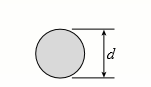
A solid round bar of aluminum having diameter d (see figure) is compressed by an axial force P = 175 kN. The bar has pinned supports and is made of alloy 2014-T6.
(a) If the diameter d = 40 mm, what is the maximum allowable length Lmax of the bar?
(b) If the length L = 0.6 m, what is the minimum required diameter dmin?
Transcribed Image Text:
d
> Determine the allowable axial load Pallow for a steel pipe column with pinned ends having an outside diameter of 220 mm and wall thickness of 12 mm for each of the following lengths: L = 2.5 m, 5 m, 7.5 m, and 10 m. (Assume E = 200 GPa and σY = 250 MPa)
> Solve the preceding problem for a W250 × 89 shape with length L = 7.5 m and E = 200 GPa. Data from Problem 5: A wide-flange steel column (E = 30 × 106 psi) of W12 × 87 shape (see figure) has a length L = 28 ft. I
> A wide-flange steel column (E = 30 × 106 psi) of W12 × 87 shape (see figure) has a length L = 28 ft. It is supported only at the ends and may buckle in any direction. Calculate the allowable load allow P based upon the critical
> Solve the preceding problem for a steel pipe column (E = 210GPa) with length L = 1.2 m, inner diameter d1 = 36 mm, and outer diameter d2 = 40 mm. Data from Problem 3: An aluminum pipe column (E = 10,400ksi) with a length L = 10.0 ft has inside and out
> An aluminum pipe column (E = 10,400ksi) with a length L = 10.0 ft has inside and outside diameters d1 = 5.0 in. and d2 = 6.0 in., respectively (see figure). The column is supported only at the ends and may buckle in any direction. Calculate the critical
> A cantilever aluminum column has a square tube cross section with an outer dimension of 150 mm. The column has a length L = 4 m and is designed to support an axial load of 45 kN. Find the minimum required thickness of the section if the factor of safety
> A frame ABCD is constructed of steel wide-flange members (W8 × 21; E = 30 × 106 psi) and subjected to triangularly distributed loads of maximum intensity qo acting along the vertical members (see figure). The distance between su
> A steel post AB with a hollow circular cross section is fixed at the base and free at the top (see figure). The inner and outer diameters are d1 = 96 mm and d2 = 110 mm, respectively, and the length is L = 4.0 m. A cable CBD passes through a fitting that
> Solve the preceding problem for an aluminum column with b = 6.0 in., t = 0.5 in., P = 30 kips, and E = 10.6 × 10³ ksi. The deflection at the top is limited to 2.0 in. Data from Problem 12: An aluminum box column with a square cross sectio
> An aluminum box column with a square cross section is fixed at the base and free at the top (see figure). The outside dimension b of each side is 100 mm and the thickness t of the wall is 8 mm. The resultant of the compressive loads acting on the top of
> The column shown in the figure is fixed at the base and free at the upper end. A compressive load P acts at the top of the column with an eccentricity e from the axis of the column. Beginning with the differential equation of the deflection curve, derive
> Determine the allowable axial load Pallow for a steel pipe column with pinned ends having an outside diameter of 4.5 in. and wall thickness of 0.237 in. for each of the following lengths: L = 6 ft, 12 ft, 18 ft, and 24 ft. (Assume E = 29,000 ksi and σY =
> Solve the preceding problem (W250 × 44.8) if the resultant force P equals 110 kN and E = 200 GPa. Data from Problem 9: A wide-flange member (W10 × 30) is compressed by axial loads that have a resultant P = 20 kips acting at t
> A wide-flange member (W10 × 30) is compressed by axial loads that have a resultant P = 20 kips acting at the point shown in the figure. The material is steel with modulus of elasticity E = 29,000 ksi. Assuming pinned-end conditions, determin
> A wide-flange member (W 200 × 22.5) is compressed by axial loads that have a resultant P acting at the point shown in the figure. The member has modulus of elasticity E = 200 GPa and pinned conditions at the ends. Lateral supports prevent an
> Solve the preceding problem for a column with e = 0.20 in., L = 12 ft, I = 21.7 in4, and E = 30 × 106 psi. Data from Problem 6: Plot the load-deflection diagram for a pinned-end column with eccentric axial loads (see figure) if the eccent
> Plot the load-deflection diagram for a pinned-end column with eccentric axial loads (see figure) if the eccentricity e of the load is 5 mm and the column has a length L = 3.6 m, moment of inertia I = 9.0 × 106 mm4, and modulus of elasticity
> Determine the bending moment M in the pinned-end column with eccentric axial loads shown in the figure. Then plot the bending-moment diagram for an axial load P = 0.3 Pcr. Note: Express the moment as a function of the distance x from the end of the colum
> A brass bar of a length L = 0.4 m is loaded at end B by force P = 10 kN with an eccentricity e = 6 mm. The bar has a rectangular cross section with an h/b ratio of 1.5. Find the dimensions of the bar if the deflection at the end is limited to 4 mm. Assum
> A simply supported slender column is subjected to axial load P = 175 kips applied at distance e = 0.5 in. from joints A and B (see figure). The column has a circular cross section with an outer diameter of 10 in. and wall thickness of 0.5 in. Calculate t
> A steel bar having a square cross section (50mm × 50mm) and length L = 2.0 m is compressed by axial loads that have a resultant P = 60 kN acting at the midpoint of one side of the cross section (see figure). Assuming that the modulus of elas
> A wide-flange column with a bracket is fixed at the base and free at the top (see figure). The column supports a load P1 = 340 kN acting at the centroid and a load P2 = 110 kN acting on the bracket at a distance s = 250 mm from the load P1. The column is
> Select a steel wide-flange column of a nominal depth of 360 mm (W 360 shape) to support an axial load P = 1100 kN (see figure). The column has pinned ends and length L = 6 m. Assume E = 200 GPa and σY = 340 MPa. A L A Section A-A H
> A W14 × 53 wide-flange column of a length L = 15 ft is fixed at the base and free at the top (see figure). The column supports a centrally applied load P1 = 120 kips and a load P2 = 40 kips supported on a bracket. The distance from the centr
> The wide-flange, pinned-end column shown in the figure carries two loads: a force P1 = 450 kN acting at the centroid and a force P2 = 270 kN acting at a distance s = 100 mm from the centroid. The column is a W250 × 67 shape with L = 4.2 m, E
> A pinned-end column with a length L = 18 ft is constructed from a W12 × 87 wide-flange shape (see figure). The column is subjected to a centrally applied load P1 = 180 kips and an eccentrically applied load P = 752 kips. The load P2 acts at
> A W310 × 74 wide-flange steel column with length L = 3.8 m is fixed at the base and free at the top (see figure). The load P acting on the column is intended to be centrally applied, but because of unavoidable discrepancies in construction,
> A steel column (E = 3 0 × 103 ksi) that is fixed at the base and free at the top is constructed of a W8 × 35 wide-flange member (see figure). The column is 9.0 ft long. The force P acting at the top of the column has an eccentri
> A W410 × 85 steel column is compressed by a force P = 340 kN acting with an eccentricity e = 38 mm, as shown in the figure. The column has pinned ends and a length L. Also, the steel has a modulus of elasticity E = 200 GPa and yield stress &
> A steel column (E = 30 × 103 ksi) with pinned ends is constructed of a W10 × 60 wide flange shape (see figure). The column is 24 ft long. The resultant of the axial loads acting on the column is a force P acting with an eccentri
> A steel W310 × 52 column is pin-supported at the ends and has a length L = 4 m. The column supports two eccentrically applied loads P1 = 750 kN and P2 = 500 kN (see figure). Bending occurs about axis 1–1 of the cross sectio
> A steel W12 × 35 column is pin-supported at the ends. The column carries an axial load P = 150 kips with eccentricity e = 3 in. (see figure). Find the length of the column if the maximum stress is restricted to the proportional limit Ï&
> A circular aluminum tube with pinned ends supports a load P = 18 kN acting at a distance e = 50 mm from the center (see figure). The length of the tube is 3.5 m, and its modulus of elasticity is 73 GPa. If the maximum permissible stress in the tube is 20
> Select a steel wide-flange column of a nominal depth of 12 in. (W 12 shape) to support an axial load P = 175 kips (see figure). The column has pinned ends and length L = 35 ft. Assume E = 29,000 ksi and σY = 36 ksi. A L A Section A-A H
> A pinned-end strut of a length L = 5.2 ft is constructed of steel pipe (E = 30 × 103 ksi) having an inside diameter d1 = 2.0 in. and outside diameter d2 = 2.2 in. (see figure). A compressive load P = 2.0 kips is applied with eccentricity e =
> A pinned-end column of a length L = 2.1 m is constructed of steel pipe (E = 210GPa) having an inside diameter d1 = 60 mm and outside diameter d2 = 68 mm (see figure). A compressive load P = 10 kN acts with eccentricity e = 30 mm. (a) What is the maximum
> A square aluminum bar with pinned ends carries a load P = 25 kips acting at distance e = 2.0 in. from the center (see figure). The bar has a length L = 54 in. and modulus of elasticity E = 10,600 ksi. If the stress in the bar is not to exceed 6 ksi, what
> A brass bar (E = 100GPa) with a square cross section is subjected to axial forces having a resultant P acting at distance e from the center (see figure). The bar is pin supported at the ends and is 0.6 m in length. The side dimension b of the bar is 30 m
> A square wood column with side dimensions b (see figure) is constructed of a structural grade of eastern white pine for which Fc = 8.0 MPa and E = 8.5 GPa. An axial force P = 100 kN acts on the column. (a) If the dimension b = 120 mm, what is the maximum
> A square wood column with side dimensions b (see figure) is constructed of a structural grade of spruce for which Fc = 900 psi and E = 1,500,000 psi. An axial force P = 8.0 kips acts on the column. (a) If the dimension b = 3.5 in, what is the maximum all
> A square wood column with side dimensions b (see figure) is constructed of a structural grade of southern pine for which Fc = 10.5 MPa and E = 12 GPa. An axial force P = 200 kN acts on the column. (a) If the dimension b = 150 mm, what is the maximum allo
> A square wood column with side dimensions b (see figure) is constructed of a structural grade of Douglas fir for which Fc = 1700 psi and E = 1,400,000 psi. An axial force P = 40 kips acts on the column. (a) If the dimension b = 5.5 in, what is the maximu
> A wood column with a rectangular cross section (see figure) is constructed of structural grade, Douglas fir lumber (Fc = 12 MPa, E = 10 GPa). The cross-sectional dimensions of the column (actual dimensions) are b = 140 mm and h = 210 mm. Determine the al
> A wood column with a rectangular cross section (see figure) is constructed of 4 in. × 8 in. construction grade, western hemlock lumber (Fc = 1000 psi, E = 1,300,000 psi). The net cross-sectional dimensions of the column are b = 3.5 in and h
> Select a steel wide-flange column of a nominal depth of 250 mm (W 250 shape) to support an axial load P = 800 kN (see figure). The column has pinned ends and length L = 4.25 m. Assume E = 200GPa and σY = 250 MPa. A L A Section A-A H
> A wood post with a rectangular cross section (see figure) is constructed of structural grade, southern pine lumber (Fc = 14 MPa, E = 12 GPa). The cross-sectional dimensions of the post (actual dimensions) are b = 100 mm and h = 150 mm. Determine the allo
> A wood post with a rectangular cross section (see figure) is constructed of 4 in. × 6 in. structural grade, Douglas fir lumber (Fc = 2000 psi, E = 1,800,000 psi). The net cross-sectional dimensions of the post are b = 3.5 in and h = 5.5 in.
> A solid round bar of aluminum having diameter d (see figure) is compressed by an axial force P = 60 kN. The bar has pinned supports and is made of alloy 6061-T6. (a) If the diameter d = 30 mm, what is the maximum allowable length Lmax of the bar? (b) If
> A solid round bar of aluminum having diameter d (see figure) is compressed by an axial force P = 10 kips. The bar has pinned supports and is made of alloy 6061-T6. (a) If the diameter d = 1.0 in, what is the maximum allowable length Lmax of the bar? (b)
> A solid round bar of aluminum having diameter d (see figure) is compressed by an axial force P = 60 kips. The bar has pinned supports and is made of alloy 2014-T6. (a) If the diameter d = 2.0 in, what is the maximum allowable length Lmax of the bar? (b)
> An aluminum pipe column (alloy 6061-T6) that is fixed at the base and free at the top has an outside diameter d2 = 80 mm and inside diameter d1 = 72 mm (see figure). Determine the allowable axial load Pallow for each of the following lengths: L = 0.6m, 0
> An aluminum pipe column (alloy 6061-T6) that is fixed at the base and free at the top has an outside diameter d2 = 3.25 in and inside diameter d1 = 3.00 in (see figure). Determine the allowable axial load Pallow for each of the following lengths: L = 2 f
> An aluminum pipe column (alloy 2014-T6) with pinned ends has an outside diameter d2 = 120 mm and inside diameter d1 = 110 mm (see figure). Determine the allowable axial load Pallow for each of the following lengths: L = 1.0 m, 2.0 m, 3.0 m, and 4.0 m.
> An aluminum pipe column (alloy 2014-T6) with pinned ends has an outside diameter d2 = 5.60 in and inside diameter d1 = 4.80 in (see figure). Determine the allowable axial load Pallow for each of the following lengths: L = 6 ft, 8 ft, 10 ft, and 12 ft.
> Determine the allowable axial load Pallow for a W10 × 60 steel wide-flange column with pinned ends (see figure) for each of the following lengths: L = 10 ft, 20 ft, 30 ft, and 40 ft. (Assume E = 29,000 ksi and σY = 36 ksi.) A
> Find the required outside diameter d for a steel pipe column (see figure) of a length L = 3.0m that is pinned at both ends and must support an axial load P = 800 kN. Assume that the wall thickness t is 9 mm. (Use E = 200 GPa and σY = 300 MPa)
> Find the required outside diameter d for a steel pipe column (see figure) of a length L = 11.5 ft that is pinned at both ends and must support an axial load P = 80 kips. Assume that the wall thickness t is 0.30 in. (Use E = 29,000 ksi and σY =
> Find the required outside diameter d for a steel pipe column (see figure) of a length L = 3.5 m that is pinned at both ends and must support an axial load P = 130 kN. Assume that the wall thickness t is equal to d/20. (Use E = 200 GPa and σY =
> Find the required outside diameter d for a steel pipe column (see figure) of a length L = 20 ft that is pinned at both ends and must support an axial load P = 25 kips. Assume that the wall thickness t is equal to d/20. (Use E = 29,000 ksi and σ
> A W 250 × 67 steel wide-flange column with pinned ends carries an axial load P. What is the maximum permissible length Lmax of the column if (a) P = 560 kN and (b) P = 890 kN? (Assume E = 200 GPa and σY = 290 MPa)
> A W 8 × 28 steel wide-flange column with pinned ends carries an axial load P. What is the maximum permissible length Lmax of the column if (a) P = 50 kips, and (b) P = 100 kips? (Assume E = 29,000 ksi and σY = 36ksi)
> The steel columns used in a college recreation center are 16.75 m long and are formed by welding three wide-flange sections (see figure). The columns are pin-supported at the ends and may buckle in any direction. Calculate the allowable load Pallow for o
> Determine the allowable axial load Pallow for a W10 × 45 steel wide-flange column with pinned ends (see figure) for each of the following lengths: L = 8 ft, 16 ft, 24 ft, and 32 ft. (Assume E = 29,000 ksi and σY = 36 ksi.) A
> A steel bar has a square cross section of width b = 2.0 in. (see figure). The bar has pinned supports at the ends and is 3.0 ft long. The axial forces acting at the end of the bar have a resultant P = 20 kips located at distance e = 0.75 in. from the cen
> An aluminum bar having a rectangular cross section (2.0in. × 1.0in.) and length L = 30 in. is compressed by axial loads that have a resultant P = 2800 lb acting at the midpoint of the long side of the cross section (see figure). Assuming tha
> A fixed-end column with circular cross section is acted on by compressive axial load P. The 18-ft-long-column has an outer diameter of 5 in, a thickness of 0.5 in., and is made of aluminum with a modulus of elasticity of 10,000 ksi. Find the buckling loa
> Column AB has a pin support at A, a roller support at B, and is compressed by an axial load P (see figure). The column is a steel W 12 × 35 with modulus of elasticity E = 29,000 ksi and proportional limit σpl = 50 ksi. The height
> A steel pipe column with pinned ends supports an axial load P = 21 kips. The pipe has outside and inside diameters of 3.5 in. and 2.9 in., respectively. What is the maximum permissible length Lmax of the column if E = 29,000 ksi and σY = 36ksi?
> Determine the maximum permissible length max L for a steel pipe column that is fixed at the base and free at the top and must support an axial load P = 500 kN (see figure). The column has an outside diameter d = 200 mm, wall thickness t = 10 mm, E = 200
> A space truss is restrained at joints O, A, B, and C, as shown in the figure. Load P is applied at joint A and load 2P acts downward at joint C. Each member is a slender, circular pipe (E = 10,600 ksi) with an outside diameter of 3.5 in. and wall thickne
> The plane truss shown in the figure supports vertical loads F at joint D, 2F at joint C, and 3F at joint B. Each member is a slender circular pipe (E = 70GPa) with an outside diameter of 60 mm and wall thickness of 5 mm. Joint B is restrained against dis
> An S6 × 12.5 steel cantilever beam AB is supported by a steel tie rod at B as shown. The tie rod is just taut when a roller support is added at C at a distance s to the left of B, then the distributed load q is applied to beam segment AC. A
> A truss ABC supports a load W at joint B, as shown in the figure. The length L1 of member AB is fixed, but the length of strut BC varies as the angle u is changed. Strut BC has a solid circular cross section. Joint B is restrained against displacement pe
> The truss ABC shown in the figure supports a vertical load W at joint B. Each member is a slender circular steel pipe (E = 30,000ksi) with an outside diameter of 4 in. and wall thickness 0.25 in. The distance between supports is 23 ft. Joint B is restrai
> The cross section of a column built up of two steel I-beams (S 150 × 25.7 sections) is shown in the figure. The beams are connected by spacer bars, or lacing, to ensure that they act together as a single column. (The lacing is represented by
> A pinned-end strut of aluminum (E = 10,400ksi) with a length L = 6 ft is constructed of circular tubing with an outside diameter d = 2 in. (see figure). The strut must resist an axial load P = 4 kips with a factor of safety n = 2.0 with respect to the cr
> Determine the maximum permissible length Lmax for a steel pipe column that is fixed at the base and free at the top and must support an axial load P = 40 kips (see figure). The column has an outside diameter d = 4.0 in, wall thickness t = 0.226 in, E = 2
> Determine the allowable axial load Pallow for a W310 × 129 steel wide-flange column with pinned ends (see figure) for each of the following lengths: L = 3 m, 6 m, 9 m, and 12 m. (Assume E = 200 GPa and σY = 340 MPa.) A L A Se
> Segments AB and BCD of beam ABCD are pin connected at x 5 10 ft. The beam is supported by a pin support at A and roller supports at C and D; the roller at D is rotated by 308 from the x axis (see figure). A trapezoidal distributed load on BC varies in in
> Segments AB and BCD of beam ABCD are pin connected at x = 4 m. The beam is supported by a sliding support at A and roller supports at C and D (see figure). A triangularly distributed load with peak intensity of 80 N/m acts on BC. A concentrated moment is
> Segments AB and BC of beam ABC are pin connected a small distance to the right of joint B (see figure). Axial loads act at A and at the mid-span of AB. A concentrated moment is applied at joint B. (a) Find reactions at supports A, B, and C. (b) Find inte
> Find support reactions at A and B and then calculate the axial force N, shear force V, and bending moment M at mid-span of AB. Let L = 4 m, q0 = 160 N/m , P = 200 N, and Mo = 380 Nm?. Mo B L/2
> Find support reactions at A and B and then calculate the axial force N, shear force V, and bending moment M at mid-span of AB. Let L = 14 ft, qo 512 lb/ft, P = 50 lb, and M0 = 300 lb-ft. Mo 4 B 3 C L L/2 A
> Two separate cables AC and BC support a sign structure of weight W = 1575 lb attached to a building. The sign is also supported by a pin support at O and a lateral restraint in the z-direction at D. (a) Find the tension in each cable. Neglect the mass of
> A round bar ABC of length 2L (see figure) rotates about an axis through the midpoint C with constant angular speed ω (radians per second). The material of the bar has weight density g. (a) Derive a formula for the tensile stress x s in the bar
> Two gondolas on a ski lift are locked in the position show in the figure while repairs are being made elsewhere. The distance between support towers is L 5100 ft. The length of each cable segment under gondolas weighing WB = 450 lb and WC =650 lb are DAB
> A crane boom of mass 450 kg with its center of mass at C is stabilized by two cables AQ and BQ (Ae = 304 mm2 for each cable) as shown in the figure. A load P = 20 kN is supported at point D. The crane boom lies in the y-z plane. (a) Find the tension forc
> An L-shaped reinforced concrete slab 12 ft × 12 ft, with a 6 ft × 6 ft cut-out and thickness t = 9.0 in, is lifted by three cables attached at O, B, and D, as shown in the figure.
> A cable and pulley system at D is used to bring a 230-kg pole (ACB) to a vertical position, as shown in the figure part a. The cable has tensile force T and is attached at C. The length L of the pole is 6.0Â m, the outer diameter is d = 140 mm
> Solve the preceding problem if the mass of the tailgate is MT = 27 kg and that of the crate is MC = 68 kg. Use dimensions H = 305 mm, LÂ =Â 406Â mm, dCÂ =Â 460 mm, and dT = 350 mm. The cable cross-se
> A pickup truck tailgate supports a crate where WC = 150 lb, as shown in the figure. The tailgate weighs WT = 60 lb and is supported by two cables (only one is shown in the figure). Each cable has an effective cross-sectional area AE = 0.017 in2. (a) Find
> Two steel wires support a moveable overhead camera weighing W = 28 lb (see figure part a) used for close-up viewing of field action at sporting events. At some instant, wire 1 is at an angle a = 228 to the horizontal and wire 2 is at angle b = 408. Wires
> A circular aluminum tube with a length of L = 420 mm is loaded in compression by forces P (see figure). The hollow segment of length L/3 has outside and inside diameters of 60 mm and 35 mm, respectively. The solid segment of length 2L/3 has a diameter of
> A circular tube AB is fixed at one end and free at the other end. The tube is subjected to axial force at joint B. If the outer diameter of the tube is 3 in. and the thickness is ¾ in., calculate the maximum normal stress in the
> A square steel tube of a length L = 20 ft and width b2 = 10.0 in. is hoisted by a crane (see figure). The tube hangs from a pin of diameter d that is held by the cables at points A and B. The cross section is a hollow square with an inner dimension b1 =
> The data shown in the accompanying table are from a tensile test of high-strength steel. The test specimen has a diameter of 0.505 in. and a gage length of 2.00 in. At fracture, the elongation between the gage marks is 0.12Â in. and the minimu
> A specimen of a methacrylate plastic is tested in tension at room temperature (see figure), producing the stress-strain data listed in the accompanying table. Plot the stress-strain curve and determine the proportional limit, modulus of elasticity (which
> The strength-to-weight ratio of a structural material is defined as its load-carrying capacity divided by its weight. For materials in tension, use a characteristic tensile stress obtained from a stress strain curve as a measure of strength. For instance
> Three different materials, designated A, B, and C, are tested in tension using test specimens having diameters of 0.505 in. and gage lengths of 2.0 in. (see figure). At failure, the distances between the gage marks are found to be 2.13, 2.48, and 2.78 in
> A steel riser pipe hangs from a drill rig located offshore in deep water. (a) What is the greatest length (meters) it can have without breaking if the pipe is suspended in the air and the ultimate strength (or breaking strength) is 550 MPa? (b) If the sa

