Question: An angle section with equal legs is
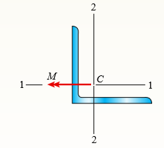
An angle section with equal legs is subjected to a bending moment M having its vector directed along the 1–1 axis, as shown in the figure.
Determine the orientation of the neutral axis and calculate the maximum tensile stress σt and maximum compressive stress σc if the angle is an L 6 × 6 × 3/4 section and M = 20 kip-in.
Transcribed Image Text:
2 м 1. M C - 1 2.
> Dimensions of cross section: b = 180 mm, t = 12 mm, h = 420 mm, h1 = 380 mm, and V = 125 kN. Data for Problem 2: A wide-flange beam (see figure) is subjected to a shear force V. Using the dimensions of the cross section, calculate the moment of inertia
> A wood beam is strengthened using two steel plates as shown in Fig. a. The beam has simple supports and an overhang and is subjected to a point load and a uniform load as shown in Fig. b. Calculate the maximum tensile and compressive stresses
> A composite beam is constructed using a steel plate (0.5 in. × 6 in.) with two wood beams (3 in. × 6 in.) on either side. The wood and steel are securely fastened to act as a single beam. The beam is subjected to a positive bend
> A wood beam reinforced by an aluminum channel section is shown in the figure. The beam has a cross section of dimensions 150 mm × 250 mm, and the channel has a uniform thickness of 6.5 mm. If the allowable stresses in the wood and aluminum a
> A wood beam reinforced using two channels is subjected to a positive bending moment Mz = 25 kip-ft. Calculate the largest tensile and compressive stresses in the wood and steel if Ew = 1500 ksi and Es = 30,000 ksi. C 8 x 11.5 Neutral hi 4 in. axis 1
> A reinforced concrete slab (see figure) is reinforced with 13-mm bars spaced 160 mm apart at d = 105 mm from the top of the slab. The modulus of elasticity for the concrete is Ec = 25 GPa, while that of the steel is Es = 200 GPa. Assume that allowable st
> A reinforced concrete T-beam (see figure) is acted on by a positive bending moment of M = 175 kip-ft. Steel reinforcement consists of four bars of 1.41-inch diameter. The modulus of elasticity for the concrete is Ec = 3000 ksi while that of the steel is
> A reinforced concrete beam (see figure) is acted on by a positive bending moment of M = 160 kN m? Steel reinforcement consists of 4Â bars of 28 mm diameter. The modulus of elasticity for the concrete is Ec = 25 GPa while that of the steel is E
> A W 12 × 50 steel wide-flange beam and a segment of a 4-inch thick concrete slab (see figure) jointly resist a positive bending moment of 95 kip-ft. The beam and slab are joined by shear connectors that are welded to the steel beam. (These c
> The cross section of a bimetallic strip is shown in the figure. Assuming that the moduli of elasticity for metals A and B are EA = 168 GPa and EB = 90 GPa, respectively, determine the smaller of the two section moduli for the beam. (Recall that section m
> A beam is constructed of two angle sections, each L 5 × 3 × 1/2, that reinforce a 2 × 8 (actual dimensions) wood plank (see the cross section shown in the figure). The modulus of elasticity for the wood is Ew = 1.2
> Two W 310 × 74 steel wide-flange beams are bolted together to form a built-up beam as shown in the figure. What is the maximum permissible bolt spacing s if the shear force V = 80 kN and the allowable load in shear on each bolt is F = 13.5 k
> The cross section of a composite beam made of aluminum and steel is shown in the figure. The moduli of elasticity are EAl = 75 GPa and Es = 200 GPa. (a) Under the action of a bending moment that produces a maximum stress of 50 MPa in the aluminum, what i
> A simple beam that is 18 ft long supports a uniform load of intensity q. The beam is constructed of two angle sections, each L 6 × 4 × 1/2, on either side of a 2 in. × 8 in. (actual dimensions) wood beam (see the cr
> Consider the preceding problem if the beam has width b = 75 mm, the aluminum strips have thickness t = 3 mm, the plastic segments have heights d = 40 mm and 3d = 120 mm, and the total height of the beam is h = 212 mm. Also, the moduli of elasticity are E
> The cross section of a beam made of thin strips of aluminum separated by a lightweight plastic is shown in the figure. The beam has width b = 3.0 in., the aluminum strips have thickness t = 0.1 in., and the plastic segments have heights d = 1.2 in. and 3
> The composite beam shown in the figure is simply supported and carries a total uniform load of 40 kN/m on a span length of 4.0 m. The beam is built of a southern pine wood member having cross- sectional dimensions of 150 mm × 250 mm and two
> A simple beam that is 18 ft long supports a uniform load of intensity q. The beam is constructed of two C 8 × 11.5 sections (channel sections or C-shapes) on either side of a 4 × 8 (actual dimensions) wood beam (see the cross se
> A simple beam of span length 3.2 m carries a uniform load of intensity 48 kN/m. The cross section of the beam is a hollow box with wood flanges and steel side plates, as shown in the figure. The wood flanges are 75 mm × 100 mm in cross secti
> A wood beam 8 in. wide and 12 in. deep (nominal dimensions) is reinforced on top and bottom by 0.25-in.-thick steel plates (see figure part a). (a) Find the allowable bending moment Mmax about the z axis if the allowable stress in the wood is 1100 psi an
> A sandwich beam having steel faces enclosing a plastic core is subjected to a bending moment M = 5 kNm? The thickness of each steel face is t = 3 mm with modulus of elasticity Es = 200 GPa. The height of the plastic core is hp = 140 mm , and its modulus
> Repeat Problem 14 but use the configuration of channel shapes and loading shown in the figure. Use P = 250 N. Data from Problem 14: A cantilever beam built up from two channel shapes, each C 200 × 17.1 and of length L, supports an incline
> The three beams shown have approximately the same cross-sectional area. Beam 1 is a W14 × 82 with flange plates; beam 2 consists of a web plate with four angles; and beam 3 is constructed of 2 C shapes with flange plates. (a) Which design ha
> A built-up I-section steel beam with channels attached to the flanges (see figure part a) is simply supported at the ends. Two equal and oppositely directed bending moments Mo act at the ends of the beam, so the beam is in pure bending. The moments act i
> A cantilever beam built up from two channel shapes, each C 200 × 17.1 and of length L, supports an inclined load P at its free end (see figure). Determine the orientation of the neutral axis and calculate the maximum tensile stress s max due
> A cantilever beam of W 12 × 14 section and length L = 9 ft supports a slightly inclined load P = 500 lb at the free end (see figure). (a) Plot a graph of the stress σA at point A as a function of the angle of inclination Î&p
> Solve the preceding problem using a W 310 × 129 section, L = 1.8 m, P = 9.5 kN, and α = 60°. Data from Problem 11: A cantilever beam with a wide-flange cross section and length L supports an inclined load P at its
> A cantilever beam with a wide-flange cross section and length L supports an inclined load P at its free end (see figure). Determine the orientation of the neutral axis and calculate the maximum tensile stress σmax due to the load P. Data for t
> A steel beam of I-section (see figure) is simply supported at the ends. Two equal and oppositely directed bending moments M0 act at the ends of the beam, so the beam is in pure bending. The moments act in plane mm, which is oriented at an angle Î&p
> A wood beam AB with a rectangular cross section (4 in. × 6 in.) serving as a roof purlin is simply supported by the top chords of two adjacent roof trusses. The beam is subjected to distributed load q acting in the vertical direction through
> A 2-m-long cantilever beam is constructed using a W 310 × 52 section. Load P acts in an inclined direction at the free end (see figure). Determine the allowable load P that can be carried by the beam if the maximum permissible tensile and co
> Solve the preceding problem for a cantilever beam with data as b = 4 in., h = 9 in., L = 10 ft, P = 325 lb, and α = 45°. Data from Problem 6: A wood cantilever beam with a rectangular cross section and length L supports an inc
> A wood cantilever beam with a rectangular cross section and length L supports an inclined load P at its free end (see figure). Determine the orientation of the neutral axis and calculate the maximum tensile stress s max due to the load P. Data for the be
> A steel beam is built up from a W 410 × 85 wide flange beam and two 180 mm × 9 mm cover plates (see figure). The allowable load in shear on each bolt is 9.8 kN. What is the required bolt spacing s in the longitudinal direction i
> Solve the preceding problem using the following data: W 8 × 21 section, L = 84 in., P = 4.5 kips, and α = 22.5°. Data from Problem 4: A simply supported wide-flange beam of span length L carries a vertical concent
> A simply supported wide-flange beam of span length L carries a vertical concentrated load P acting through the centroid C at the midpoint of the span (see figure). The beam is attached to supports inclined at an angle a to the horizontal. Determine the o
> Solve the preceding problem for the following data: b = 6 in., h = 10 in., L = 12.0 ft, tan α = 1/3, and q = 325 lb/ft. Data from Problem 2: A wood beam with a rectangular cross section (see figure) is simply supported on a span of lengt
> A wood beam with a rectangular cross section (see figure) is simply supported on a span of length L. The longitudinal axis of the beam is horizontal, and the cross section is tilted at an angle α. The load on the beam is a vertical uniform
> A cold-formed steel section is made by folding a steel plate to form a structural section such as that shown in the figure. This beam is subjected to bending moment M = 2 kip-in. at angle θ = 10° to the z axis. Find the centroid a
> A C 200 × 17.1 channel section has an angle with equal legs attached as shown; the angle serves as a lintel beam. The combined steel section is subjected to a bending moment M having its vector directed along the z axis, as shown in the figu
> A steel post (E = 30 × 106 psi) having thickness t = 1/8 in and height L = 72 in supports a stop sign (see figure). The stop sign post is subjected to a bending moment M having its vector at an angle θ to the z axis. Determine t
> A built-up beam supporting a condominium balcony is made up of a structural T (one half of a W 200 × 31.3) for the top flange and web and two angles (2 L 102 × 76 × 6.4, long legs back-to-back) for the bottom flange
> A beam with a semicircular cross section of radius r is subjected to a bending moment M having its vector at an angle θ to the z axis (see figure). Derive formulas for the maximum tensile stress σt and the maximum compressive stre
> The cross section of a steel beam is shown in the figure. This beam is subjected to a bending moment M having its vector at an angle θ to the z axis. Determine the orientation of the neutral axis and calculate the maximum tensile stress &Ium
> The T-beam shown in the figure is fabricated by welding together two steel plates. If the allowable load for each weld is 1.8 kips/in. in the longitudinal direction, what is the maximum allowable shear force V? 0.6 in. 5.5 in. C -4s in - To.s in. 4.
> The cross section of a steel beam is constructed of a W 18 × 71 wide-flange section with a 6 in. × 1/2 in. cover plate welded to the top flange and a C 10 × 30 channel section welded to the bottom flange. This beam
> The Z-section of Example D-7 is subjected to M = 5 kNm?, as shown. Determine the orientation of the neutral axis and calculate the maximum tensile stress σt and maximum compressive stress σc in the beam. Use the following numerical
> A beam made up of two unequal leg angles is subjected to a bending moment M having its vector at an angle θ to the z axis (see figure part a). (a) For the position shown in the figure, determine the orientation of the neutral axis and calcul
> An angle section with equal legs is subjected to a bending moment M having its vector directed along the 1–1 axis, as shown in the figure. Determine the orientation of the neutral axis and calculate the maximum tensile stress Ï
> A beam with a channel section is subjected to a bending moment M having its vector at an angle θ to the z axis (see figure). Determine the orientation of the neutral axis and calculate the maximum tensile stress σt and maximum com
> Solve the preceding problem for a W 200 × 41.7 shape with b = 166 mm, h = 205 mm, tw = 7.24 mm, tf = 11.8mm, and V = 38 kN. Data from Problem 3: A beam of wide-flange shape, W 8 × 28, has the cross section shown in the figure
> A beam of wide-flange shape, W 8 × 28, has the cross section shown in the figure. The dimensions are b = 6.54 in, h = 8.06 in, tw = 0.285 in, and tf = 0.465 in. The loads on the beam produce a shear force V = 7.5 kips at the cross section un
> Solve the preceding problem for a W 250 × 44.8 wide-flange shape with L = 3.5 m, q = 45 kN/m, h = 267 mm, b = 148 mm, tf = 13 mm, tw = 7.62 mm, d = 0.5 m, and a = 50 mm. Data from Problem 1: A simple beam with a W 10 × 30 wid
> A cross section in the shape of a circular arc of constant thickness is shown in the figure. Derive the following formula for the distance e from the center of the arc to the shear center S: in which β is in radians. Also, plot a graph showin
> A beam of a T cross section is formed by nailing together two boards having the dimensions shown in the figure. If the total shear force V acting on the cross section is 1500 N and each nail may carry 760 N in shear, what is the maximum allowable nail sp
> The cross section of a sign post of constant thickness is shown in the figure. Derive the formula for the distance e from the centerline of the wall of the post to the shear center S: where Iz = moment of inertia about the axis. Also, compare this formul
> Derive the following formula for the distance e from the centerline of the wall to the shear center S for the hat section of constant thickness shown in the figure: Also, check the formula for the special case of a channel section (a = 0). Зы* (Ь +
> Derive the following formula for the distance e from the centerline of the wall to the shear center S for the C-section of constant thickness shown in the figure: Also, check the formula for the special cases of a channel section (a = 0) and a slit recta
> A U-shaped cross section of constant thickness is shown in the figure. Derive the following formula for the distance e from the center of the semicircle to the shear center S: Also, plot a graph showing how the distance e (expressed as the non dimensiona
> The cross section of a slit rectangular tube of constant thickness is shown in the figures. (a) Derive the following formula for the distance e from the centerline of the wall of the tube in the figure part a to the shear center S: (b) Find an expression
> The cross section of a slit circular tube of constant thickness is shown in the figure. (a) Show that the distance e from the center of the circle to the shear center S is equal to 2r in the figure part a. (b) Find an expression for e if flanges with the
> The cross section of a channel beam with double flanges and constant thickness throughout the section is shown in the figure. Derive the following formula for the distance e from the centerline of the web to the shear center S: 362(목 + h) 서 + 6b(A +
> A load P acts on a horizontal beam that is supported by four rods arranged in the symmetrical pattern shown in the figure. Each rod has a cross- sectional area A, and the material is elastoplastic with a yield stress σY. Determine the plastic
> A horizontal rigid bar AB supporting a load P is hung from five symmetrically placed wires, each of cross-sectional area A (see figure). The wires are fastened to a curved surface of radius R. (a) Determine the plastic load PP if the material of the wire
> A hollow wood beam with plywood webs has the cross-sectional dimensions shown in the figure. The plywood is attached to the flanges by means of small nails. Each nail has an allowable load in shear of 30 lb. Find the maximum allowable spacing s of the na
> A stepped bar ACB with circular cross sections is held between rigid supports and loaded by an axial force P at mid length (see figure). The diameters for the two parts of the bar are d1 = 20 mm and d2 = 25 mm, and the material is elastoplastic with yiel
> Two identical bars AB and BC support a vertical load P (see figure). The bars are made of steel having a stress-strain curve that may be idealized as elastoplastic with yield stress σY. Each bar has cross-sectional area A. Determine the yield
> An aluminum bar subjected to tensile forces P has a length L = 150 in. and cross-sectional area A = 2.0 in2 The stress-strain behavior of the aluminum may be represented approximately by the bilinear stress-strain diagram shown in the figure. Calculate t
> A prismatic bar in tension has a length L = 2.0m and cross-sectional area A = 249 mm2. The material of the bar has the stress-strain curve shown in the figure. Determine the elongation d of the bar for each of the following axial loads: P = 10 kN, 20 kN,
> A hollow circular tube T of a length L = 15 in is uniformly compressed by a force P acting through a rigid plate (see figure). The outside and inside diameters of the tube are 3.0 and 2.75 in., respectively. A concentric solid circular bar B of 1.5 in. d
> Two cables, each having a length L of approximately 40 m, support a loaded container of weight W (see figure). The cables, which have an effective cross- sectional area A = 48.0mm2 and effective modulus of elasticity E = 160 GPa, are identical except tha
> The structure shown in the figure consists of a horizontal rigid bar ABCD supported by two steel wires: one of length L and the other of length 3L/4. Both wires have cross-sectional area A and are made of elastoplastic material with yield stress Ï&#
> Two wood box beams (beams A and B) have the same outside dimensions (200 mm × 360 mm) and the same thickness (t = 2 0mm) throughout, as shown in the figure. Both beams are formed by nailing, with each nail having an allowable shear load of 2
> A rigid bar ACB is supported on a fulcrum at C and loaded by a force P at end B (see figure). Three identical wires made of an elastoplastic material (yield stress σY and modulus of elasticity E) resist the load P. Each wire has cross-sectiona
> A circular steel rod AB with a diameter d = 0.60 in is stretched tightly between two supports so that (initially) the tensile stress in the rod is 10 ksi (see figure). An axial force P is then applied to the rod at an intermediate location C. (a) Determi
> Five bars, each having a diameter of 10 mm, support a load P as shown in the figure. Determine the plastic load PP if the material is elastoplastic with yield stress σY = 250 MPa. トー6一一6一6→6→ 26
> The symmetric truss ABCDE shown in the figure is constructed of four bars and supports a load P at joint E. Each of the two outer bars has a cross-sectional area of 0.307 in2, and each of the two inner bars has an area of 0.601 in2. The material is elast
> Determine the plastic modulus Z and shape factor f for a W 12 × 14 wide-flange beam. Obtain the cross-sectional dimensions and section modulus of the beam in Appendix F.
> Solve the preceding problem for a wide flange beam with h = 404 mm, b = 140 mm, tf = 11.2 mm, and tw = 6.99 mm. Data from Problem 5: Calculate the shape factor f for the wide flange beam shown in the figure if h = 12.2 in, b = 8.08 in, tf = 0.64 in, a
> Calculate the shape factor f for the wide flange beam shown in the figure if h = 12.2 in, b = 8.08 in, tf = 0.64 in, and tw = 0.37 in. h C - tw b.
> A steel beam of rectangular cross section is 40 mm wide and 80 mm high (see figure). The yield stress of the steel is 210 MPa. (a) What percent of the cross-sectional area is occupied by the elastic core if the beam is subjected to a bending moment of 12
> A propped cantilever beam of length L = 54 in with a sliding support supports a uniform load of intensity q (see figure). The beam is made of steel (σY = 3 6ksi) and has a rectangular cross section of width b = 4.5 in and height h = 6.0 in. Wh
> Wires B and C are attached to a support at the left-hand end and to a pin-supported rigid bar at the right-hand end (see figure). Each wire has cross-sectional area A = 0.03in2 and modulus of elasticity E = 30 × 106 psi. When the bar is in a
> A box beam is constructed of four wood boards as shown in the figure part a. The webs are 8 in. × 1 in. and the flanges are 6 in. × 1 in. boards (actual dimensions), joined by screws for which the allowable load in shear is F =
> A stepped bar with a hole (see figure) has widths b = 2.4 in. and c = 1.6 in. The fillets have radii equal to 0.2 in. What is the diameter dmax of the largest hole that can be drilled through the bar without reducing the load-carrying capacity? P
> A non prismatic bar ABC made up of segments AB (length L1, cross-sectional area A1) and BC (length L2, cross-sectional area A2) is fixed at end A and free at end C (see figure). The modulus of elasticity of the bar is E. A small gap of dimension s exists
> Pipe 2 has been inserted snugly into Pipe 1, but the holes for a connecting pin do not line up; there is a gaps. The user decides to apply either force P1 to Pipe 1 or force P2 to Pipe 2, whichever is smaller. Determine the following using the numerical
> A bar AB having a length L and axial rigidity EA is fixed at end A (see figure). At the other end, a small gap of dimension s exists between the end of the bar and a rigid surface. A load P acts on the bar at point C, which is two-thirds of the length fr
> The mechanical assembly shown in the figure consists of an aluminum tube, a rigid end plate, and two steel cables. The slack is removed from the cables by rotating the turnbuckles until the assembly is snug but with no initial stresses. Afterward, the tu
> A steel wire AB is stretched between rigid supports (see figure). The initial pre stress in the wire is 42 MPa when the temperature is 20° C. (a) What is the stress σ in the wire when the temperature drops to 0° C? (b) At
> A copper bar AB with a length 25 in. and diameter 2 in. is placed in position at room temperature with a gap of 0.008 in. between end A and a rigid restraint (see figure). The bar is supported at end B by an elastic spring with a spring constant k = 1.2
> A rigid bar ABCD is pinned at end A and supported by two cables at points B and C (see figure). The cable at B has a nominal diameter dB = 12 mm and the cable at C has a nominal diameter dC = 20 mm. A load P acts at end D of the bar. What is the allowabl
> A rigid triangular frame is pivoted at C and held by two identical horizontal wires at points A and B (see figure). Each wire has an axial rigidity EA = 120 kips and coefficient of thermal expansion α = 12. 5 × 10⁻⁶/°
> A brass sleeve S is fitted over a steel bolt B (see figure), and the nut is tightened until it is just snug. The bolt has a diameter dB = 25 mm, and the sleeve has inside and outside diameters d1 = 26 mm and d2 = 36 mm, respectively. Calculate the temper
> Rectangular bars of copper and aluminum are held by pins at their ends, as shown in the figure. Thin spacers provide a separation between the bars. The copper bars have cross-sectional dimensions 0.5 in × 2.0 in, and the aluminum bar has dim
> A wood box beam is constructed of two 260 mm × 50 mm boards and two 260 mm × 25 mm boards (see figure). The boards are nailed at a longitudinal spacing s = 100 mm. If each nail has an allowable shear force F = 1200 N, what is th
> A circular, aluminum alloy bar of a length L = 1.8 m has a slot in the middle half of its length (see figure). The bar has a radius r = 36 mm and modulus of elasticity E = 72 GPa. The slot has a height 2a = r/4. If the temperature of the beam is raised u
> A circular steel rod AB (diameter d1 = 1.0 in., length L1 = 3.0 ft) has a bronze sleeve (outer diameter d2 = 1.25 in., length L2 = 1.0 ft) shrunk onto it so that the two parts are securely bonded (see figure). Calculate the total elongation d of the stee
> Repeat Problem 9 for the flat bar shown in the figure but assume that ∆T = 30° C, and that α = 19 × 1026 /°C, L = 2 m, t = 20 mm, b1 = 100 mm, b2 = 115 mm, and E = 96 GPa. Data from Pro
> A flat aluminum alloy bar is fixed at both ends. Segment AB has a slight taper. If the temperature of the bar is raised uniformly by an amount ∆T = 20° F, find reactions at A and C. What is the displacement at B? Assume that

