Question: Determine the fixed-end moments (MA and
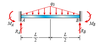
Determine the fixed-end moments (MA and MB) and fixed-end forces (RA and RB) for a beam of length L supporting a triangular load of maximum intensity q0 (see figure). Then draw the shear-force and bending-moment diagrams, labeling all critical ordinates.
Transcribed Image Text:
go LA MA В MB RA RB L 2
> A cantilever beam is supported at B by cable BC. The beam carries a uniform load q = 200 N/m. If the length of the beam is L = 3 m, find the force in the cable and the reactions at A. Ignore the axial flexibility of the cable. C B, -L -
> A fixed-end beam AB supports a uniform load of intensity q = 75 lb/ft acting over part of the span. Assume that EI = 300 kip-ft2. (a) Calculate the reactions at A and B. (b) Find the maximum displacement and its location. (c) Repeat part (a) if the distr
> A cable CD of a length H is attached to the third point of a simple beam AB of a length L (see figure). The moment of inertia of the beam is I, and the effective cross-sectional area of the cable is A. The cable is initially taut but without any initial
> A two-span, continuous wood girder (E = 1700 ksi) supports a roof patio structure (figure part a). A uniform load of intensity q acts on the girder, and each span is of length 8 ft. The girder is made up using two 2 × 8 wood members (see fig
> Repeat Problem 15 using L = 3.5 m, δmax = 3 mm, and EI = 800kN·m2. Data from Problem 15: A propped cantilever beam is subjected to uniform load q. The beam has flexural rigidity EI = 2000 kip-ft2 and the length of the beam i
> A propped cantilever beam is subjected to uniform load q. The beam has flexural rigidity EI = 2000 kip-ft2 and the length of the beam is 10 ft. Find the intensity q of the distributed load if the maximum displacement of the beam is δmax = 0.
> A propped cantilever beam of a length L is loaded by a concentrated moment M0 at midpoint C. Use the second-order differential equation of the deflection curve to solve for reactions at A and B. Draw shear-force and bending-moment diagrams for the entire
> A counterclockwise moment M0 acts at the midpoint of a fixed-end beam ACB of length L (see figure). Beginning with the second-order differential equation of the deflection curve (the bending- moment equation), determine all reactions of the beam and obta
> A fixed-end beam AB carries point load P acting at point C. The beam has a rectangular cross section (b = 75 mm, h = 150 mm). Calculate the reactions of the beam and the displacement at point C. Assume that E = 190 GPa. P= 5 kN 3 m m- C B L = 5 m
> A fixed-end beam of a length L is loaded by triangularly distributed load of a maximum intensity q0 at B. Use the fourth-order differential equation of the deflection curve to solve for reactions at A and B and also the equation of the deflection curve.
> A fixed-end beam of a length L is loaded by a distributed load in the form of a cosine curve with a maximum intensity q0 at A. (a) Use the fourth-order differential equation of the deflection curve to solve for reactions at A and B and also the equation
> A cantilever beam has a length L and is loaded by a triangularly distributed load of maximum intensity q0 at B. Use the fourth-order differential equation of the deflection curve to solve for reactions at A and B and also the equation of the deflection c
> A cantilever beam of a length L and loaded by a uniform load of intensity q has a fixed support at A and spring support at B with rotational stiffness kR. A rotation θB at B results in a reaction moment MB = kR × θB
> A cantilever beam AB of a length L has a fixed support at A and a roller support at B (see figure). The support at B is moved downward through a distance δB. Using the fourth-order differential equation of the deflection curve (the load equa
> A fixed-end beam AB of a length L supports a uniform load of intensity q (see figure). Beginning with the second-order differential equation of the deflection curve (the bending- moment equation), obtain the reactions, shear forces, bending moments, slop
> A propped cantilever beam AB of a length L is loaded by a counterclockwise moment M0 acting at support B (see figure). Beginning with the second-order differential equation of the deflection curve (the bending-moment equation), obtain the reactions, shea
> Solve the preceding problem by integrating the differential equation of the deflection curve. Data from Problem 4: A two-span beam with spans of lengths L and L/3 is subjected to a temperature differential with temperature T1 on its upper surface and
> A fixed-end beam is subjected to a point load at mid-span. The beam has a rectangular cross section (assume that the h/b ratio is 2) and is made of wood (E = 1 1 GPa). (a) Find height h of the cross section if the maximum displacement of the beam is 2 mm
> A propped cantilever steel beam is constructed from a W12 × 35 section. The beam is loaded by its self-weight with intensity q. The length of the beam is 11.5 ft. Let E = 30,000 ksi. (a) Calculate the reactions at joints A and B. (b) Find th
> A propped cantilever beam is loaded by two different load patterns (see figures a and b). Assume that EI is constant and the total beam length is L. Find expressions for reactions at A and B for each beam. Plot shear and moment diagrams. Assu
> Repeat Problem 41 for the loading shown in the figure. Data from Problem 41: Find an expression for required moment MA (in terms of q and L) that will result in rotation θA = 0 due to MA and q loadings applied at the same time. MA A
> Find an expression for required moment MA (in terms of q and L) that will result in rotation θA = 0 due to MA and q loadings applied at the same time. MA EI, L B 2L L 3 3
> A thin steel beam AB used in conjunction with an electromagnet in a high-energy physics experiment is securely bolted to rigid supports (see figure). A magnetic field produced by coils C results in a force acting on the beam. The force is trapezoid ally
> A beam supporting a uniform load of intensity q throughout its length rests on pistons at points A, C, and B (see figure). The cylinders are filled with oil and are connected by a tube so that the oil pressure on each piston is the same. The pistons at A
> A wide-flange beam ABC rests on three identical spring supports at points A, B, and C (see figure). The flexural rigidity of the beam is EI = 6912 × 106 lb-in2, and each spring has stiffness k = 62,500 lb/in. The length of the beam is L = 16
> The continuous frame ABC has a pinned support at A, a sliding support at C, and a rigid corner connection at B (see figure). Members AB and BC each have length L and flexural rigidity EI. A horizontal force P acts at mid-height of member AB. (a) Find all
> A two-span beam with spans of lengths L and L/3 is subjected to a temperature differential with temperature T1 on its upper surface and T2 on its lower surface (see figure). (a) Determine all reactions for this beam. Use the method of superposition in th
> The continuous frame ABC has a fixed support at A, a roller support at C, and a rigid corner connection at B (see figure). Members AB and BC each have length L and flexural rigidity EI. A horizontal force P acts at mid-height of member AB. (a) Find all r
> The beam AB shown in the figure is simply supported at A and B and supported on a spring of stiffness k at its midpoint C. The beam has flexural rigidity EI and length 2L. What should be the stiffness k of the spring in order that the maximum bending mom
> The cantilever beam AB shown in the figure is an S6 × 12.5 steel I-beam with E = 30 × 106 psi. The simple beam DE is a wood beam 4in. × 12in. (nominal dimensions) in cross section with E = 1.5 × 10⁶ psi
> Two identical, simply supported beams AB and CD are placed so that they cross each other at their midpoints (see figure). Before the uniform load is applied, the beams just touch each other at the crossing point. Determine the maximum bending moments (MA
> A temporary wood flume serving as a channel for irrigation water is shown in the figure. The vertical boards forming the sides of the flume are sunk in the ground, which provides a fixed support. The top of the flume is held by tie rods that are tightene
> A fixed-end beam AB of a length L is subjected to a moment M0 acting at the position shown in the figure. (a) Determine all reactions for this beam. (b) Draw shear-force and bending-moment diagrams for the special case in which a = b = L/2. M, B A M
> A propped cantilever beam is loaded by a triangular distributed load from A to C (see figure). The load has a peak intensity qo = 10 lb/ft. The length of the beam is 12 ft. Find support reactions at A and B. go
> A propped cantilever beam is subjected to two triangularly distributed loads, each with a peak load intensity equal to q0 (see figure). Find the expressions for reactions at A and C using superposition. Plot shear and moment diagrams. 90 B L L 2 EI
> A beam rests on supports at A and B and is loaded by a distributed load with intensity q as shown. A small gap D exists between the unloaded beam and the support at C. Assume that span length L = 40 in. and flexural rigidity of the beam EI = 0.4 Ã
> A three-span continuous beam ABCD with three equal spans supports a uniform load of intensity q (see figure). Determine all reactions of this beam and draw the shear-force and bending-moment diagrams, labeling all critical ordinates. A B |RD -- Rc R
> Solve the preceding problem by integrating the differential equation of the deflection curve. Data from Problem 2: A propped cantilever beam, fixed at the left-hand end A and simply supported at the right hand end B, is subjected to a temperature diff
> A beam ABC is fixed at end A and supported by beam DE at point B (see figure). Both beams have the same cross section and are made of the same material. (a) Determine all reactions due to the load P. (b) What is the numerically largest bending moment in
> The figure shows a non prismatic, propped cantilever beam AB with flexural rigidity 2EI from A to C and EI from C to B. Determine all reactions of the beam due to the uniform load of intensity q. B EI C A 2EI MA RA L RB L 2
> A cantilever beam is supported by a tie rod at B as shown. Both the tie rod and the beam are steel with E = 30 × 106 psi. The tie rod is just taut before the distributed load q = 200 lb/ft is applied. (a) Find the tension force in the tie ro
> A propped cantilever beam with a length L = 4 m is subjected to a trapezoidal load with intensities q0 = 10 kN/m and q1 = 15 kN/m. Find the reactions at A and B. go B IA
> Uniform load q = 10 lb/ft acts over part of the span of fixed-end beam AB (see figure). Upward load P = 250 lb is applied 9 ft to the right of joint A. Find the reactions at A and B. 9 ft 6 ft P LA B L= 15 ft
> A fixed-end beam is loaded by a uniform load q = 15 kN/m and a point load P = 30 kN at mid span. The beam has a length of 4 m and modulus of elasticity of 205 GPa. (a) Find reactions at A and B. (b) Calculate the height of the beam if the displacement at
> A triangularly distributed load with a maximum intensity of qo = 10 lb/ft acts on propped cantilever beam AB. If the length L of the beam is 10 ft, find the reactions at A and B. go B IA
> A propped cantilever beam has flexural rigidity EI = 4.5 MN·m2. When the loads shown are applied to the beam, it settles at joint B by 5 mm. Find the reaction at joint B 5 kN/m 2 kN -- B, C A MA -5 mm settlement 4 m- 2 m- RA 1 m RB
> Beam ABC is fixed at support A and rests (at point B) upon the midpoint of beam DE (see part a of the figure). Thus, beam ABC may be represented as a propped cantilever beam with an overhang BC and a linearly elastic support of stiffness k at
> A continuous beam ABC with two unequal spans, one of length L and one of length 2L, supports a uniform load of intensity q (see figure). Determine the reactions RA, RB, and RC for this beam. Also, draw the shear-force and bending-moment diagrams, labelin
> A propped cantilever beam, fixed at the left-hand end A and simply supported at the right hand end B, is subjected to a temperature differential with temperature T1 on its upper surface and T2 on its lower surface (see figure). (a) Find all reactions for
> A propped cantilever beam of a length 2L is loaded by a uniformly distributed load with intensity q. The beam is supported at B by a linearly elastic rotational spring with stiffness kR, which provides a resisting moment MB due to rotation θ
> A propped cantilever beam of a length 2L is loaded by a uniformly distributed load with intensity q. The beam is supported at B by a linearly elastic spring with stiffness k. Use the method of superposition to solve for all reactions. Also draw shear-for
> Two flat beams AB and CD, lying in horizontal planes, cross at right angles and jointly support a vertical load P at their midpoints (see figure). Before the load P is applied, the beams just touch each other. Both beams are made of the same material and
> The continuous frame ABCD has a pin support at B; roller supports at A, C, and D; and rigid corner connections at B and C (see figure). Members AB, BC, and CD each have flexural rigidity EI. Moment M0 acts counterclockwise at B and clockwise at C. Note:
> Beam AB has a pin support at A and a roller support at B. Joint B is also restrained by a linearly elastic rotational spring with stiffness kR, which provides a resisting moment MB due to rotation at B. Member AB has flexural rigidity EI. A moment M0 act
> The continuous frame ABC has a pin support at A, roller supports at B and C, and a rigid corner connection at B (see figure). Members AB and BC each have flexural rigidity EI. A moment M0 acts counterclockwise at A. Note: Disregard axial deformations in
> The continuous frame ABC has a pin support at A, roller supports at B and C, and a rigid corner connection at B (see figure). Members AB and BC each have flexural rigidity EI. A moment M0 acts counterclockwise at B. Note: Disregard axial deformations in
> A propped cantilever beam of a length 2L with a support at B is loaded by a uniformly distributed load with intensity q. Use the method of superposition to solve for all reactions. Also draw shear-force and bending-moment diagrams, labeling all critical
> A beam with a sliding support at B is loaded by a uniformly distributed load with intensity q. Use the method of superposition to solve for all reactions. Also draw shear-force and bending-moment diagrams, labeling all critical ordinates. MB B A MA
> (a) A simple beam AB with length L and height h supports a uniform load of intensity q (see the figure part a). Obtain a formula for the curvature shortening l of this beam. Also, obtain a formula for the maximum bending stress σb in the beam
> The cross section of a rectangular beam having a width b and height h is shown in part a of the figure. For reasons unknown to the beam designer, it is planned to add structural projections of width b/9 and height d to the top and bottom of the beam (see
> A beam of square cross section (a = length of each side) is bent in the plane of a diagonal (see figure). By removing a small amount of material at the top and bottom corners, as shown by the shaded triangles in the figure, you can increase the section m
> A retaining wall (Fig. a) is constructed using steel W-shape columns and concrete panel infill (Fig. b). Each column is subjected to lateral soil pressure with peak intensity qo (Figs. b and c). The tensile and compressive strength of the beam is 600 MPa
> A retaining wall 6 ft high is constructed of horizontal wood planks 2.5 in. thick (actual dimension) that are supported by vertical wood piles of a 12 in. diameter (actual dimension), as shown in the figure. The lateral earth pressure is p1 = 125 lb/ft2
> A steel beam ABC is simply supported at A and B and has an overhang BC of length L = 150 mm (see figure). The beam supports a uniform load of intensity q = 4.0 kN/m over its entire span AB and 1.5q over BC. The cross section of the beam is rectangular wi
> A steel plate (called a cover plate) having cross-sectional dimensions 6.0 in × 0.5 in is welded along the full length of the bottom flange of a W 12 × 50 wide-flange beam (see figure, which shows the beam cross section). What i
> A horizontal shelf AD of length L = 1215 mm, width b = 305 mm, and thickness t = 22 mm is supported by brackets at B and C (see part a of the figure). The brackets are adjustable and may be placed in any desired positions between the ends of the shelf. A
> Determine the ratios of the weights of four beams that have the same length, are made of the same material, are subjected to the same maximum bending moment, and have the same maximum bending stress if their cross sections are (1) a rectangle with height
> A beam having a cross section in the form of a channel (see figure) is subjected to a bending moment acting about the z axis. Calculate the thickness t of the channel in order that the bending stresses at the top and bottom of the beam will be in the rat
> A beam having a cross section in the form of an un symmetric wide-flange shape (see figure) is subjected to a negative bending moment acting about the z axis. Determine the width b of the top flange in order that the stresses at the top and bottom of the
> While drilling a hole with a brace and bit, you exert a downward force P = 25 lb on the handle of the brace (see figure). The diameter of the crank arm is d = 7/16 in. and its lateral offset is b = 4-7/8 in. Determine the maximum tensile and compressive
> A small balcony constructed of wood is supported by three identical cantilever beams (see figure). Each beam has length L1 = 2.1 m, width b, and height h = 4b/3. The dimensions of the balcony floor are L1 × L2, where L2 = 2.5 m. The design l
> A propped cantilever beam ABC (see figure) has a shear release just right of the mid-span. (a) Select the most economical wood beam from the table in Appendix G; assume q = 55 lb/ft, L = 16 ft, σaw = 1750 psi, and τaw = 375 psi. Inc
> A cantilever beam AB with a circular cross section and length L = 750 mm supports a load P = 800 N acting at the free end (see figure). The beam is made of steel with an allowable bending stress of 120 MPa. (a) Determine the required diameter dmin (figur
> A two-axle carriage that is part of an overhead traveling crane in a testing laboratory moves slowly across a simple beam AB (see figure). The load transmitted to the beam from the front axle is 2200 lb and from the rear axle is 3800 lb. The weight of th
> A “trapeze bar” in a hospital room provides a means for patients to exercise while in bed (see figure). The bar is 2.1 m long and has a cross section in the shape of a regular octagon. The design load is 1.2 kN applied
> A beam ABC with an overhang from B to C is constructed of a C 10 × 03 channel section with flanges facing upward (see figure). The beam supports its own weight (30 lb/ft) plus a triangular load of maximum intensity qo acting on the overhang.
> The wood joists supporting a plank floor (see figure) are 38 mm × 220 mm in cross section (actual dimensions) and have a span length of L = 4.0 m. The floor load is 5.0 kPa, which includes the weight of the joists and the floor. (a) Calculat
> A floor system in a small building consists of wood planks supported by 2-in. (nominal width) joists spaced at distance s and measured from center to center (see figure). The span length L of each joist is 12 ft, the spacing s of the joists is 16 in., an
> A pontoon bridge (see figure) is constructed of two longitudinal wood beams, known as balks, that span between adjacent pontoons and support the transverse floor beams, which are called chesses. For purposes of design, assume that a uniform floor load of
> A simple beam AB is loaded as shown in the figure. (a) Calculate the required section modulus S if σallow = 18,000 psi, L = 32 ft, P = 2900 lb, and q = 450 lb/ft. Then select a suitable I-beam (S shape) from, Appendix F, and recalculate S taki
> A solid circular pole is subjected to linearly varying distributed force with maximum intensity qo at the base and an axial compressive load P at the top (see figure). Find the required diameter d of the pole if the maximum allowable normal stress is 150
> A simple beam of length L = 5 m carries a uniform load of intensity q = 5.8 kN/m and a concentrated load 22.5 kN (see figure). (a) Assuming σallow = 110 MPa, calculate the required section modulus S. Then select the most economical wide-flange
> A cantilever beam AB is loaded by a uniform load q and a concentrated load P, as shown in the figure. (a) Select the most economical steel C shape in Appendix F; use q = 20 lb/ft and P = 300 lb. (b) Select the most economical steel S shape in Appendix F;
> A fiberglass bracket ABCD with a solid circular cross section has the shape and dimensions shown in the figure. A vertical load P = 40 N acts at the free end D. (a) Determine the minimum permissible diameter mind of the bracket if the allowable bending s
> The cross section of a narrow-gage railway bridge is shown in part a of the figure. The bridge is constructed with longitudinal steel girders that support the wood cross ties. The girders are restrained against lateral buckling by diagonal bracing, as in
> Solve the preceding problem for a bar of monel metal having the following properties: d1 = 1.0 in., d2 = 1.4 in., L1 = 20.0 in., L2 = 5.0 in., and E = 25 × 106 psi. Also, the bar lengthens by 0.0040 in. when the tensile load is applied. Da
> A round brass bar of a diameter d1 = 20 mm has upset ends each with a diameter d2 = 26 mm (see figure). The lengths of the segments of the bar are L1 = 0.3 m and L2 = 0.1 m. Quarter-circular fillets are used at the shoulders of the bar, and the modulus o
> A flat bar of width b and thickness t has a hole of diameter d drilled through it (see figure). The hole may have any diameter that will fit within the bar. What is the maximum permissible tensile load Pmax if the allowable tensile stress in the material
> The flat bars shown in parts a and b of the figure are subjected to tensile forces P = 2.5 kN. Each bar has thickness t = 5.0 mm. (a) For the bar with a circular hole, determine the maximum stresses for hole diameters d = 12 mm and d = 20 mm if the width
> The flat bars shown in parts a and b of the figure are subjected to tensile forces P = 3.0 kips. Each bar a has thickness t = 0.25 in. (a) For the bar with a circular hole, determine the maximum stresses for hole diameters d = 1 in. and d = 2 in. if the
> A simply supported beam (L = 4.5 m) must support mechanical equipment represented as a distributed load with intensity q = 30 kN/m acting over the middle segment of the beam (see figure). Select the most economical W-shape steel beam to support the loads
> Draw the shear-force and bending-moment diagrams for a cantilever beam AB carrying a uniform load of intensity q over one-half of its length (see figure). A B L 2
> A simple beam AB is subjected to a counterclockwise couple of moment Mo acting at distance a from the left-hand support (see figure). Draw the shear force and bending-moment diagrams for this beam. Also draw the shear-force and bending-moment diagrams if
> Draw the shear-force and bending-moment diagrams for a simple beam AB supporting two equal concentrated loads P (see figure). Repeat if the left-hand load is upward and the right-hand load is downward. |P B
> The centrifuge shown in the figure rotates in a horizontal plane (the x-y plane) on a smooth surface about the z axis (which is vertical) with an angular acceleration α. Each of the two arms has a weight w per unit length and supports a wei
> The simply supported beam ABCD is loaded by a weight W = 27 kN through the arrangement shown in the figure part a. The cable passes over a small frictionless pulley at B and is attached at E to the end of the vertical arm. (a) Calculate the axial force N
> Frame ABC has a moment release just left of joint B. Find axial force N, shear force V, and moment M at the top of column AB. Write variables N, V, and M in terms of variables P and L. P Moment release L/4 L/4 C B N, V, Mat L L/2 P L/2 A
> Frame ABCD carries two concentrated loads (2P at C and P at D, see figure) and also a linearly varying distributed load on AB. Find expressions for shear force V and moment M at x = L/3 of beam AB in terms of peak load intensity qo, force P, and beam len
> A cable with force P is attached to a frame at D and runs over a frictionless pulley at B. Find expressions for shear force V and moment M at x = L/3 of beam AB. L/3 C Di Cable L/3 L/3 B A 2L/3 V, Mat L/3
> Find expressions for shear force V and moment M at x = L/2 of beam AB in structure (a) Express V and M in terms of peak load intensity qo and beam length variable L. Repeat for structure (b) but find V and M at mid-span of member BC. g0 A 4L/5 B L/

