Question: A cantilever beam model is often used
A cantilever beam model is often used to represent micro-electrical-mechanical systems (MEMS) (see figure). The cantilever beam is made of polysilicon (E = 150GPa) and is subjected to an electrostatic moment M applied at the end of the cantilever beam. If dimensions are b = 2 μm, h = 4 μm, and L = 320 μm, find expressions for the tip deflection and rotation of the cantilever beam in terms of moment M.
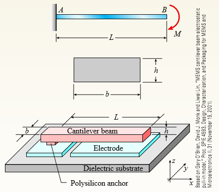
Transcribed Image Text:
LA B M -L- h – L – Cantilever beam Electrode Dielectric substrate Polysilicon anchor Based on Gary O'Brien, David J. Mank and Liwei Lin, "MEMS cantilever beam electrostatic pull-in model," Proc. SPIE 4593, Design, Characterization, and Packaging for MEMS and Microelectronics II, 31 (November 19, 2001).
> Beam AB has an elastic support kR at A, pin support at B, length L, height h (see figure), and is heated in such a manner that the temperature difference T2 – T1 between the bottom and top of the beam is proportional to the distance fro
> The load on a cantilever beam AB has a triangular distribution with maximum intensity qo (see figure). Determine the angle of rotation θB and the deflection dB at the free end. 90 B A L-
> Repeat Problem 10, but now use the tapered propped cantilever tube AB with sliding support at B (see figure) that supports a concentrated load P at the sliding end. Find the equation of the deflection curve and the deflection δB at the slidi
> A tapered cantilever beam AB supports a concentrated load P at the free end (see figure). The cross sections of the beam are rectangular tubes with constant width b, outer tube depth dA at A, and outer tube depth dB = 3dA/2 at support B. The tube thickne
> A simple beam ABC has a moment of inertia 1.5I from A to B and I from B to C (see figure). A concentrated load P acts at point B. Obtain the equations of the deflection curves for both parts of the beam. From the equations, determine the angles of rotati
> A beam ABC has a rigid segment from A to B and a flexible segment with moment of inertia I from B to C (see figure). A concentrated load P acts at point B. Determine the angle of rotation θA of the rigid segment, the deflection dB at point B
> A simple beam ABCD has moment of inertia I near the supports and moment of inertia 2I in the middle region, as shown in the figure. A uniform load of intensity q acts over the entire length of the beam. Determine the equations of the deflection curve for
> A simple beam AB of length L and height h (see figure) is heated in such a manner that the temperature difference T2 – T1 between the bottom and top of the beam is proportional to the distance from support A; that is, assume the tempera
> Beam ACB hangs from two springs, as shown in the figure. The springs have stiffnesses k1 and k2, and the beam has flexural rigidity EI. (a) What is the downward displacement of point C, which is at the midpoint of the beam, when the moment Mo is applied?
> The cantilever beam ACB shown in the figure supports a uniform load of intensity q throughout its length. The beam has moments of inertia I2 and I1 in parts AC and CB, respectively. (a) Using the method of superposition, determine the deflection Î&
> The frame shown in the figure consists of a beam ACB supported by a strut CD. The beam has length 2L and is continuous through joint C. A concentrated load P acts at the free end B. Determine the vertical deflection δB at point B due to the
> A simple beam ACB supporting a uniform load q over the first half of the beam and a couple of moment Mo at end B is shown in the figure. Determine the strain energy U stored in the beam due to the load q and the couple Mo acting simultaneously. Mo A
> A beam ABC with simple supports at A and B and an overhang BC supports a concentrated load P at the free end C (see figure). (a) Determine the strain energy U stored in the beam due to the load P. (b) From the strain energy, find the deflection Î&a
> A simple beam AB of length L is subjected to loads that produce a symmetric deflection curve with maximum deflection δ at the midpoint of the span (see figure). How much strain energy U is stored in the beam if the deflection curve is (a) a
> A propped cantilever beam AB of length L and with a sliding support at A supports a uniform load of intensity q (see figure). (a) Evaluate the strain energy of the beam from the bending moment in the beam. (b) Evaluate the strain energy of the beam from
> A simple beam AB of length L supports a concentrated load P at the midpoint (see figure). (a) Evaluate the strain energy of the beam from the bending moment in the beam. (b) Evaluate the strain energy of the beam from the equation of the deflection curve
> A symmetric beam ABCD with overhangs at both ends supports a uniform load of intensity q (see figure). Determine the deflection δD at the end of the overhang. (Obtain the solution by using the modified form of Castigliano’s
> An overhanging beam ABC rests on a simple support at A and a spring support at B (see figure). A concentrated load P acts at the end of the overhang. Span AB has length L, the overhang has length a, and the spring has stiffness k. Determine the downward
> An overhanging beam ABC of height h has a sliding support at A and a roller at B. The beam is heated to a temperature T1 on the top and T2 on the bottom (see figure). Determine the equation of the deflection curve of the beam, the angle of rotation &Icir
> An overhanging beam ABC is subjected to a couple MA at the free end (see figure). The lengths of the overhang and the main span are a and L, respectively. Determine the angle of rotation A u and deflection δA at end A. (Obtain the solution b
> A simple beam ABCDE supports a uniform load of intensity q (see figure). The moment of inertia in the central part of the beam (BCD) is twice the moment of inertia in the end parts (AB and DE). Find the deflection δC at the midpoint C of the
> The frame ABC supports a concentrated load P at point C (see figure). Members AB and BC have lengths h and b, respectively. Determine the vertical deflection δC and angle of rotation θC at end C of the frame. (Obtain the solutio
> The cantilever beam ACB shown in the figure is subjected to a uniform load of intensity q acting between points A and C. Determine the angle of rotation θA at the free end A. (Obtain the solution by using the modified form of Castigliano&aci
> A cantilever beam ACB supports two concentrated loads P1 and P2, as shown in the figure. Determine the deflections δC and δB at points C and B, respectively. (Obtain the solution by using the modified form of Castiglianoâ&
> A simple beam ACB supports a uniform load of intensity q on the left-hand half of the span (see figure). Determine the angle of rotation θB at support B. (Obtain the solution by using the modified form of Castigliano’s theo
> A simple beam AB of length L and height h undergoes a temperature change such that the bottom of the beam is at temperature T2 and the top of the beam is at temperature T1 (see figure). Determine the equation of the deflection curve of the beam, the angl
> A heavy object of weight W is dropped onto the midpoint of a simple beam AB from a height h (see figure). Obtain a formula for the maximum bending stress σmax due to the falling weight in terms of h, σst, and δ, where &
> A simple beam AB of length L is loaded at the left-hand end by a couple of moment Mo (see figure). Determine the angle of rotation θA at support A. (Obtain the solution by determining the strain energy of the beam and then using Castigliano&
> A uniformly loaded simple beam AB (see figure) of a span length L and a rectangular cross section (b = width, h = height) has a maximum bending stress σmax due to the uniform load q. Determine the strain energy U stored in the beam. A B L
> The cantilever beam ACB shown in the figure has moments of inertia I2 and I1 in parts AC and CB, respectively. (a) Using the method of superposition, determine the deflection δB at the free end due to the load P. (b) Determine the ratio r of
> A cantilever beam AB is subjected to a uniform load of intensity q acting throughout its length (see figure). Determine the angle of rotation θB and the deflection δB at the free end. I4 B -L-
> A simply supported beam (E = 1600 ksi) is loaded by a triangular distributed load from A to C (see figure). The load has a peak intensity qo = 10 lb/ft, and the deflection is known to be 0.01 in. at point C. The length of the beam is 12 ft, and the ratio
> Derive the equation of the deflection curve for a cantilever beam AB when a couple Mo acts counterclockwise at the free end (see figure). Also, determine the deflection dB and slope θB at the free end. Use the third-order differential equati
> The cantilever beam shown in the figure supports a triangularly distributed load of maximum intensity qo. Determine the deflection δB at the free end B. (Obtain the solution by determining the strain energy of the beam and then using Castigl
> A simply supported beam is loaded with a point load, as shown in the figure. The beam is a steel wide flange shape (W 12 × 35) in strong axis bending. Calculate the maximum deflection of the beam and the rotation at joint A if L = 10 ft, a =
> The beam shown in the figure has a sliding support at A and a roller support at B. The sliding support permits vertical movement but no rotation. Derive the equation of the deflection curve and determine the deflection δA at end A and also &
> Derive the equations of the deflection curve for a simple beam AB with a distributed load of peak intensity qo acting over the left-hand half of the span (see figure). Also, determine the deflection δC at the midpoint of the beam. Use the se
> Derive the equations of the deflection curve for a cantilever beam AB supporting a distributed load of peak intensity qo acting over one-half of the length (see figure). Also, obtain formulas for the deflections δB and δC at poi
> An overhanging beam ABC supports a concentrated load P at the end of the overhang (see figure). Span AB has length L, and the overhang has length a. Determine the deflection δC at the end of the overhang. (Obtain the solution by determining
> Derive the equations of the deflection curve for a cantilever beam AB carrying a uniform load of intensity q over part of the span (see figure). Also, determine the deflection δB at the end of the beam. Use the second-order differential equa
> Derive the equations of the deflection curve for a simple beam AB loaded by a couple Mo acting at distance a from the left-hand support (see figure). Also, determine the deflection δo at the point where the load is applied. Use the second-or
> The beam shown in the figure has a sliding support at A and a spring support at B. The sliding support permits vertical movement but no rotation. Derive the equation of the deflection curve and determine the deflection δB at end B due to the
> A simple beam with an overhang is subjected to a point load P = 6 kN. If the maximum allowable deflection at point C is 0.5 mm, select the lightest W360 section that can be used for the beam. Assume that L = 3 m and ignore the distributed weight of the b
> A cantilever beam has a length L = 12 ft and a rectangular cross section (b = 16 in, h = 24 in). A linearly varying distributed load with peak intensity qo acts on the beam. (a) Find peak intensity qo if the deflection at joint B is known to be 0.18 in.
> A cantilever beam AB supporting a triangularly distributed load of maximum intensity qo is shown in the figure. Derive the equation of the deflection curve and then obtain formulas for the deflection dB and angle of rotation θB at the free e
> Derive the equation of the deflection curve for a simple beam AB loaded by a couple Mo at the left-hand support (see figure). Also, determine the maximum deflection δmax. Use the second-order differential equation of the deflection curve.
> Derive the equation of the deflection curve for a cantilever beam AB supporting a load P at the free end (see figure). Also, determine the deflection δB and angle of rotation θB at the free end. Use the second-order differential
> Beams AB and CDE are connected using rigid link DB with hinges (or moment releases) at ends D and B (see figure a). Beam AB is fixed at joint A and beam CDE is pin-supported at joint E. Load P = 150 lb is applied at C. (a) Calculate the deflections of jo
> The simple beam shown in the figure supports a concentrated load P acting at distance a from the left-hand support and distance b from the right-hand support. Determine the deflection δD at point D where the load is applied. (Obtain the solu
> Obtain a formula for the ratio δC/δmax of the deflection at the midpoint to the maximum deflection for a simple beam supporting a concentrated load P (see figure). From the formula, plot a graph of δC/δ
> A cantilever beam with a uniform load (see figure) has a height h equal to 1/8 of the length L. The beam is a steel wide-flange section with E = 28 × 106 psi and an allowable bending stress of 17,500 psi in both tension and compression. Calc
> What is the span length L of a uniformly loaded, simple beam of wide-flange cross section (see figure) if the maximum bending stress is 12,000 psi, the maximum deflection is 0.1 in., the height of the beam is 12 in., and the modulus of elasticity is E =
> A uniformly loaded, steel wide-flange beam with simple supports (see figure) has a downward deflection of 10 mm at the midpoint and angles of rotation equal to 0.01 radians at the ends. Calculate the height h of the beam if the maximum bending stress is
> A 1-meter-long, simply supported copper beam (E = 117 GPa) carries uniformly distributed load q. The maximum deflection is measured as 1.5 mm. (a) Calculate the magnitude of the distributed load q if the beam has a rectangular cross section (width b = 20
> Derive the equations of the deflection curve for beam AB with sliding support at A and roller support at B, supporting a distributed load of maximum intensity qo acting on the right-hand half of the beam (see figure). Also, determine deflection Î&a
> A cantilever beam AB of length L and height h (see figure) is subjected to a temperature change such that the temperature at the top is T1 and at the bottom is T2. Determine the equation of the deflection curve of the beam, the angle of rotation Î&
> A propped cantilever beam AB of a length L carries a concentrated load P acting at the position shown in the figure. Determine the reactions RA, RB, and MA for this beam. Also, draw the shear-force and bending- moment diagrams, labeling all critical ordi
> A cantilever beam is supported at B by cable BC. The beam carries a uniform load q = 200 N/m. If the length of the beam is L = 3 m, find the force in the cable and the reactions at A. Ignore the axial flexibility of the cable. C B, -L -
> A fixed-end beam AB supports a uniform load of intensity q = 75 lb/ft acting over part of the span. Assume that EI = 300 kip-ft2. (a) Calculate the reactions at A and B. (b) Find the maximum displacement and its location. (c) Repeat part (a) if the distr
> A cable CD of a length H is attached to the third point of a simple beam AB of a length L (see figure). The moment of inertia of the beam is I, and the effective cross-sectional area of the cable is A. The cable is initially taut but without any initial
> A two-span, continuous wood girder (E = 1700 ksi) supports a roof patio structure (figure part a). A uniform load of intensity q acts on the girder, and each span is of length 8 ft. The girder is made up using two 2 × 8 wood members (see fig
> Repeat Problem 15 using L = 3.5 m, δmax = 3 mm, and EI = 800kN·m2. Data from Problem 15: A propped cantilever beam is subjected to uniform load q. The beam has flexural rigidity EI = 2000 kip-ft2 and the length of the beam i
> A propped cantilever beam is subjected to uniform load q. The beam has flexural rigidity EI = 2000 kip-ft2 and the length of the beam is 10 ft. Find the intensity q of the distributed load if the maximum displacement of the beam is δmax = 0.
> A propped cantilever beam of a length L is loaded by a concentrated moment M0 at midpoint C. Use the second-order differential equation of the deflection curve to solve for reactions at A and B. Draw shear-force and bending-moment diagrams for the entire
> A counterclockwise moment M0 acts at the midpoint of a fixed-end beam ACB of length L (see figure). Beginning with the second-order differential equation of the deflection curve (the bending- moment equation), determine all reactions of the beam and obta
> A fixed-end beam AB carries point load P acting at point C. The beam has a rectangular cross section (b = 75 mm, h = 150 mm). Calculate the reactions of the beam and the displacement at point C. Assume that E = 190 GPa. P= 5 kN 3 m m- C B L = 5 m
> A fixed-end beam of a length L is loaded by triangularly distributed load of a maximum intensity q0 at B. Use the fourth-order differential equation of the deflection curve to solve for reactions at A and B and also the equation of the deflection curve.
> A fixed-end beam of a length L is loaded by a distributed load in the form of a cosine curve with a maximum intensity q0 at A. (a) Use the fourth-order differential equation of the deflection curve to solve for reactions at A and B and also the equation
> A cantilever beam has a length L and is loaded by a triangularly distributed load of maximum intensity q0 at B. Use the fourth-order differential equation of the deflection curve to solve for reactions at A and B and also the equation of the deflection c
> A cantilever beam of a length L and loaded by a uniform load of intensity q has a fixed support at A and spring support at B with rotational stiffness kR. A rotation θB at B results in a reaction moment MB = kR × θB
> A cantilever beam AB of a length L has a fixed support at A and a roller support at B (see figure). The support at B is moved downward through a distance δB. Using the fourth-order differential equation of the deflection curve (the load equa
> A fixed-end beam AB of a length L supports a uniform load of intensity q (see figure). Beginning with the second-order differential equation of the deflection curve (the bending- moment equation), obtain the reactions, shear forces, bending moments, slop
> A propped cantilever beam AB of a length L is loaded by a counterclockwise moment M0 acting at support B (see figure). Beginning with the second-order differential equation of the deflection curve (the bending-moment equation), obtain the reactions, shea
> Solve the preceding problem by integrating the differential equation of the deflection curve. Data from Problem 4: A two-span beam with spans of lengths L and L/3 is subjected to a temperature differential with temperature T1 on its upper surface and
> A fixed-end beam is subjected to a point load at mid-span. The beam has a rectangular cross section (assume that the h/b ratio is 2) and is made of wood (E = 1 1 GPa). (a) Find height h of the cross section if the maximum displacement of the beam is 2 mm
> A propped cantilever steel beam is constructed from a W12 × 35 section. The beam is loaded by its self-weight with intensity q. The length of the beam is 11.5 ft. Let E = 30,000 ksi. (a) Calculate the reactions at joints A and B. (b) Find th
> A propped cantilever beam is loaded by two different load patterns (see figures a and b). Assume that EI is constant and the total beam length is L. Find expressions for reactions at A and B for each beam. Plot shear and moment diagrams. Assu
> Repeat Problem 41 for the loading shown in the figure. Data from Problem 41: Find an expression for required moment MA (in terms of q and L) that will result in rotation θA = 0 due to MA and q loadings applied at the same time. MA A
> Find an expression for required moment MA (in terms of q and L) that will result in rotation θA = 0 due to MA and q loadings applied at the same time. MA EI, L B 2L L 3 3
> A thin steel beam AB used in conjunction with an electromagnet in a high-energy physics experiment is securely bolted to rigid supports (see figure). A magnetic field produced by coils C results in a force acting on the beam. The force is trapezoid ally
> A beam supporting a uniform load of intensity q throughout its length rests on pistons at points A, C, and B (see figure). The cylinders are filled with oil and are connected by a tube so that the oil pressure on each piston is the same. The pistons at A
> A wide-flange beam ABC rests on three identical spring supports at points A, B, and C (see figure). The flexural rigidity of the beam is EI = 6912 × 106 lb-in2, and each spring has stiffness k = 62,500 lb/in. The length of the beam is L = 16
> The continuous frame ABC has a pinned support at A, a sliding support at C, and a rigid corner connection at B (see figure). Members AB and BC each have length L and flexural rigidity EI. A horizontal force P acts at mid-height of member AB. (a) Find all
> A two-span beam with spans of lengths L and L/3 is subjected to a temperature differential with temperature T1 on its upper surface and T2 on its lower surface (see figure). (a) Determine all reactions for this beam. Use the method of superposition in th
> The continuous frame ABC has a fixed support at A, a roller support at C, and a rigid corner connection at B (see figure). Members AB and BC each have length L and flexural rigidity EI. A horizontal force P acts at mid-height of member AB. (a) Find all r
> The beam AB shown in the figure is simply supported at A and B and supported on a spring of stiffness k at its midpoint C. The beam has flexural rigidity EI and length 2L. What should be the stiffness k of the spring in order that the maximum bending mom
> The cantilever beam AB shown in the figure is an S6 × 12.5 steel I-beam with E = 30 × 106 psi. The simple beam DE is a wood beam 4in. × 12in. (nominal dimensions) in cross section with E = 1.5 × 10⁶ psi
> Two identical, simply supported beams AB and CD are placed so that they cross each other at their midpoints (see figure). Before the uniform load is applied, the beams just touch each other at the crossing point. Determine the maximum bending moments (MA
> A temporary wood flume serving as a channel for irrigation water is shown in the figure. The vertical boards forming the sides of the flume are sunk in the ground, which provides a fixed support. The top of the flume is held by tie rods that are tightene
> A fixed-end beam AB of a length L is subjected to a moment M0 acting at the position shown in the figure. (a) Determine all reactions for this beam. (b) Draw shear-force and bending-moment diagrams for the special case in which a = b = L/2. M, B A M
> A propped cantilever beam is loaded by a triangular distributed load from A to C (see figure). The load has a peak intensity qo = 10 lb/ft. The length of the beam is 12 ft. Find support reactions at A and B. go
> A propped cantilever beam is subjected to two triangularly distributed loads, each with a peak load intensity equal to q0 (see figure). Find the expressions for reactions at A and C using superposition. Plot shear and moment diagrams. 90 B L L 2 EI
> A beam rests on supports at A and B and is loaded by a distributed load with intensity q as shown. A small gap D exists between the unloaded beam and the support at C. Assume that span length L = 40 in. and flexural rigidity of the beam EI = 0.4 Ã
> A three-span continuous beam ABCD with three equal spans supports a uniform load of intensity q (see figure). Determine all reactions of this beam and draw the shear-force and bending-moment diagrams, labeling all critical ordinates. A B |RD -- Rc R
> Solve the preceding problem by integrating the differential equation of the deflection curve. Data from Problem 2: A propped cantilever beam, fixed at the left-hand end A and simply supported at the right hand end B, is subjected to a temperature diff
> A beam ABC is fixed at end A and supported by beam DE at point B (see figure). Both beams have the same cross section and are made of the same material. (a) Determine all reactions due to the load P. (b) What is the numerically largest bending moment in
> The figure shows a non prismatic, propped cantilever beam AB with flexural rigidity 2EI from A to C and EI from C to B. Determine all reactions of the beam due to the uniform load of intensity q. B EI C A 2EI MA RA L RB L 2
> A cantilever beam is supported by a tie rod at B as shown. Both the tie rod and the beam are steel with E = 30 × 106 psi. The tie rod is just taut before the distributed load q = 200 lb/ft is applied. (a) Find the tension force in the tie ro
> A propped cantilever beam with a length L = 4 m is subjected to a trapezoidal load with intensities q0 = 10 kN/m and q1 = 15 kN/m. Find the reactions at A and B. go B IA
> Uniform load q = 10 lb/ft acts over part of the span of fixed-end beam AB (see figure). Upward load P = 250 lb is applied 9 ft to the right of joint A. Find the reactions at A and B. 9 ft 6 ft P LA B L= 15 ft

