Question: The frame ABC supports a concentrated load
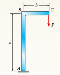
The frame ABC supports a concentrated load P at point C (see figure). Members AB and BC have lengths h and b, respectively.
Determine the vertical deflection δC and angle of rotation θC at end C of the frame. (Obtain the solution by using the modified form of Castigliano’s theorem.)
Transcribed Image Text:
B В. C P h
> A beam ABCD consisting of a simple span BD and an overhang AB is loaded by a force P acting at the end of the bracket CEF (see figure). (a) Determine the deflection δA at the end of the overhang. (b) Under what conditions is this deflection
> A cantilever beam is subjected to a quadratic distributed load q(x) over the length of the beam (see figure). Find an expression for moment M in terms of the peak distributed load intensity qo so that the deflection is δB = 0. q(x) = qo
> Repeat Problem 15 for the anti- symmetric loading shown in the figure. Data from Problem 15: Use the method of superposition to find the angles of rotation θA and θB at the supports, and the maximum deflection δm
> Use the method of superposition to find the angles of rotation θA and θB at the supports, and the maximum deflection δmax for a simply supported beam subjected to symmetric loads P at distance a from each support. A
> A cantilever beam is subjected to load P at mid-span and counterclockwise moment M at B (see figure). (a) Find an expression for moment M in terms of the load P so that the reaction moment MA at A is equal to zero. (b) Find an expression for moment M in
> The cantilever beam ACB shown in the figure has flexural rigidity EI = 2.1 × 10⁶ kip-in2. Calculate the downward deflections δC and dB at points C and B, respectively, due to the simultaneous action of the moment of 35 kip-in. a
> A cantilever beam AB of length L = 6 ft is constructed of a W8 × 21 wide-flange section (see figure). A weight W = 1500 lb falls through a height h = 0.25 in onto the end of the beam. Calculate the maximum deflection δmax of the
> Determine the angle of rotation uB and deflection dB at the free end of a cantilever beam AB having a uniform load of intensity q acting over the middle third of its length (see figure). L
> What must be the equation y = f(x) of the axis of the slightly curved beam AB (see figure) before the load is applied in order that the load P, moving along the bar, always stays at the same level? |P B X- 7- L.
> Beam ACB hangs from two springs, as shown in the figure. The springs have stiffnesses k1 and k2 and the beam has flexural rigidity EI. (a) What is the downward displacement of point C, which is at the midpoint of the beam, when the moment Mo is applied?
> The cantilever beam AB shown in the figure has an extension BCD attached to its free end. A force P acts at the end of the extension. (a) Find the ratio a/L so that the vertical deflection of point B will be zero. (b) Find the ratio a/L so that the angle
> A simple beam AB supports five equally spaced loads P (see figure). (a) Determine the deflection δ1 at the midpoint of the beam. (b) If the same total load (5P) is distributed as a uniform load on the beam, what is the deflection Î&acu
> A cantilever beam AB carries three equally spaced concentrated loads, as shown in the figure. Obtain formulas for the angle of rotation θB and deflection δB at the free end of the beam. L L 3
> A cantilever beam carries a trapezoidal distributed load (see figure). Let wB = 2.5 kN/m, wA = 5.0 kN/m, and L = 2.5 m. The beam has a modulus E = 45 GPa and a rectangular cross section with width b = 200 mm and depth h = 300 mm. WA WB B LA L h
> A cantilever beam of a length L = 2.5 ft has a rectangular cross section (b = 4 in, h = 8 in) and modulus E = 10,000 ksi. The beam is subjected to a linearly varying distributed load with a peak intensity qo = 900 lb/ft. go A. B L
> Beam ABC is loaded by a uniform load q and point load P at joint C. Using the method of superposition, calculate the deflection at joint C. Assume that L = 4 m, a = 2 m, q = 15 kN/m , P = 7.5 kN , E = 200 GPa, and I = 70.8 × 106 mm4. C
> Copper beam AB has circular cross section with a radius of 0.25 in. and length L = 3 ft. The beam is subjected to a uniformly distributed load w = 3.5 lb/ft. Calculate the required load P at joint B so that the total deflection at joint B is zero. Assume
> An object of weight W is dropped onto the midpoint of a simple beam AB from a height h (see figure). The beam has a rectangular cross section of area A. Assuming that h is very large compared to the deflection of the beam when the weight W is applied sta
> A simply supported beam (E = 1 2 GPa) carries a uniformly distributed load q = 125 N/m, and a point load P = 200 N at mid-span. The beam has a rectangular cross section (b = 75 mm, h = 200 mm) and a length of 3.6 m. Calculate the maximum deflection of th
> A simple beam AB is subjected to couples Mo and 2Mo acting as shown in the figure. Determine the angles of rotation θ A and θ B at the ends of the beam and the deflection δ at point D where the load Mo is applied.
> The simple beam AB shown in the figure supports two equal concentrated loads P: one acting downward and the other upward. Determine the angle of rotation θA at the left hand end, the deflection δ1 under the downward load, and th
> A simple beam AB is subjected to a load in the form of a couple Mo acting at end B (see figure). Determine the angles of rotation θA and θB at the supports and the deflection δ at the midpoint. Mo A B L
> A simple beam AB supports two concentrated loads P at the positions shown in the figure. A support C at the midpoint of the beam is positioned at distance d below the beam before the loads are applied. Assuming that d = 10 mm, L = 6 m, E = 200 GPa, and I
> Obtain formulas for the angle of rotation θA at support A and the deflection δmax at the midpoint for a simple beam AB with a uniform load of intensity q (see figure). A B L
> A cantilever beam ACB supports two concentrated loads P1 and P2, as shown in the figure. Calculate the deflections dB and dC at points B and C, respectively. Assume P1 = 10 kN, P2 = 5 kN, L = 2.6 m, E = 200 GPa, and I = 20.1 × 106 mm4.
> Calculate the deflections δB and δC at points B and C, respectively, of the cantilever beam ACB shown in the figure. Assume Mo = 36 kip-in, P = 3.8 kips, L = 8 ft, and EI = 2.25 × 10⁹ lb-in2. Mo
> Determine the angle of rotation θB and the deflection δB at the free end of a cantilever beam AB with a uniform load of intensity q acting over the middle third of the length (see figure). 14 B L L L 3 3 3
> A cantilever beam AB is subjected to a concentrated load P and a couple Mo acting at the free end (see figure). Obtain formulas for the angle of rotation θB and the deflection δB at end B. |P 14 B' Mo L
> Beam AB has an elastic support kR at A, pin support at B, length L, height h (see figure), and is heated in such a manner that the temperature difference T2 – T1 between the bottom and top of the beam is proportional to the distance fro
> The load on a cantilever beam AB has a triangular distribution with maximum intensity qo (see figure). Determine the angle of rotation θB and the deflection dB at the free end. 90 B A L-
> Repeat Problem 10, but now use the tapered propped cantilever tube AB with sliding support at B (see figure) that supports a concentrated load P at the sliding end. Find the equation of the deflection curve and the deflection δB at the slidi
> A tapered cantilever beam AB supports a concentrated load P at the free end (see figure). The cross sections of the beam are rectangular tubes with constant width b, outer tube depth dA at A, and outer tube depth dB = 3dA/2 at support B. The tube thickne
> A simple beam ABC has a moment of inertia 1.5I from A to B and I from B to C (see figure). A concentrated load P acts at point B. Obtain the equations of the deflection curves for both parts of the beam. From the equations, determine the angles of rotati
> A beam ABC has a rigid segment from A to B and a flexible segment with moment of inertia I from B to C (see figure). A concentrated load P acts at point B. Determine the angle of rotation θA of the rigid segment, the deflection dB at point B
> A simple beam ABCD has moment of inertia I near the supports and moment of inertia 2I in the middle region, as shown in the figure. A uniform load of intensity q acts over the entire length of the beam. Determine the equations of the deflection curve for
> A simple beam AB of length L and height h (see figure) is heated in such a manner that the temperature difference T2 – T1 between the bottom and top of the beam is proportional to the distance from support A; that is, assume the tempera
> Beam ACB hangs from two springs, as shown in the figure. The springs have stiffnesses k1 and k2, and the beam has flexural rigidity EI. (a) What is the downward displacement of point C, which is at the midpoint of the beam, when the moment Mo is applied?
> The cantilever beam ACB shown in the figure supports a uniform load of intensity q throughout its length. The beam has moments of inertia I2 and I1 in parts AC and CB, respectively. (a) Using the method of superposition, determine the deflection Î&
> The frame shown in the figure consists of a beam ACB supported by a strut CD. The beam has length 2L and is continuous through joint C. A concentrated load P acts at the free end B. Determine the vertical deflection δB at point B due to the
> A simple beam ACB supporting a uniform load q over the first half of the beam and a couple of moment Mo at end B is shown in the figure. Determine the strain energy U stored in the beam due to the load q and the couple Mo acting simultaneously. Mo A
> A beam ABC with simple supports at A and B and an overhang BC supports a concentrated load P at the free end C (see figure). (a) Determine the strain energy U stored in the beam due to the load P. (b) From the strain energy, find the deflection Î&a
> A simple beam AB of length L is subjected to loads that produce a symmetric deflection curve with maximum deflection δ at the midpoint of the span (see figure). How much strain energy U is stored in the beam if the deflection curve is (a) a
> A propped cantilever beam AB of length L and with a sliding support at A supports a uniform load of intensity q (see figure). (a) Evaluate the strain energy of the beam from the bending moment in the beam. (b) Evaluate the strain energy of the beam from
> A simple beam AB of length L supports a concentrated load P at the midpoint (see figure). (a) Evaluate the strain energy of the beam from the bending moment in the beam. (b) Evaluate the strain energy of the beam from the equation of the deflection curve
> A symmetric beam ABCD with overhangs at both ends supports a uniform load of intensity q (see figure). Determine the deflection δD at the end of the overhang. (Obtain the solution by using the modified form of Castigliano’s
> An overhanging beam ABC rests on a simple support at A and a spring support at B (see figure). A concentrated load P acts at the end of the overhang. Span AB has length L, the overhang has length a, and the spring has stiffness k. Determine the downward
> An overhanging beam ABC of height h has a sliding support at A and a roller at B. The beam is heated to a temperature T1 on the top and T2 on the bottom (see figure). Determine the equation of the deflection curve of the beam, the angle of rotation &Icir
> An overhanging beam ABC is subjected to a couple MA at the free end (see figure). The lengths of the overhang and the main span are a and L, respectively. Determine the angle of rotation A u and deflection δA at end A. (Obtain the solution b
> A simple beam ABCDE supports a uniform load of intensity q (see figure). The moment of inertia in the central part of the beam (BCD) is twice the moment of inertia in the end parts (AB and DE). Find the deflection δC at the midpoint C of the
> The cantilever beam ACB shown in the figure is subjected to a uniform load of intensity q acting between points A and C. Determine the angle of rotation θA at the free end A. (Obtain the solution by using the modified form of Castigliano&aci
> A cantilever beam ACB supports two concentrated loads P1 and P2, as shown in the figure. Determine the deflections δC and δB at points C and B, respectively. (Obtain the solution by using the modified form of Castiglianoâ&
> A simple beam ACB supports a uniform load of intensity q on the left-hand half of the span (see figure). Determine the angle of rotation θB at support B. (Obtain the solution by using the modified form of Castigliano’s theo
> A simple beam AB of length L and height h undergoes a temperature change such that the bottom of the beam is at temperature T2 and the top of the beam is at temperature T1 (see figure). Determine the equation of the deflection curve of the beam, the angl
> A heavy object of weight W is dropped onto the midpoint of a simple beam AB from a height h (see figure). Obtain a formula for the maximum bending stress σmax due to the falling weight in terms of h, σst, and δ, where &
> A simple beam AB of length L is loaded at the left-hand end by a couple of moment Mo (see figure). Determine the angle of rotation θA at support A. (Obtain the solution by determining the strain energy of the beam and then using Castigliano&
> A uniformly loaded simple beam AB (see figure) of a span length L and a rectangular cross section (b = width, h = height) has a maximum bending stress σmax due to the uniform load q. Determine the strain energy U stored in the beam. A B L
> The cantilever beam ACB shown in the figure has moments of inertia I2 and I1 in parts AC and CB, respectively. (a) Using the method of superposition, determine the deflection δB at the free end due to the load P. (b) Determine the ratio r of
> A cantilever beam AB is subjected to a uniform load of intensity q acting throughout its length (see figure). Determine the angle of rotation θB and the deflection δB at the free end. I4 B -L-
> A simply supported beam (E = 1600 ksi) is loaded by a triangular distributed load from A to C (see figure). The load has a peak intensity qo = 10 lb/ft, and the deflection is known to be 0.01 in. at point C. The length of the beam is 12 ft, and the ratio
> Derive the equation of the deflection curve for a cantilever beam AB when a couple Mo acts counterclockwise at the free end (see figure). Also, determine the deflection dB and slope θB at the free end. Use the third-order differential equati
> The cantilever beam shown in the figure supports a triangularly distributed load of maximum intensity qo. Determine the deflection δB at the free end B. (Obtain the solution by determining the strain energy of the beam and then using Castigl
> A simply supported beam is loaded with a point load, as shown in the figure. The beam is a steel wide flange shape (W 12 × 35) in strong axis bending. Calculate the maximum deflection of the beam and the rotation at joint A if L = 10 ft, a =
> The beam shown in the figure has a sliding support at A and a roller support at B. The sliding support permits vertical movement but no rotation. Derive the equation of the deflection curve and determine the deflection δA at end A and also &
> Derive the equations of the deflection curve for a simple beam AB with a distributed load of peak intensity qo acting over the left-hand half of the span (see figure). Also, determine the deflection δC at the midpoint of the beam. Use the se
> Derive the equations of the deflection curve for a cantilever beam AB supporting a distributed load of peak intensity qo acting over one-half of the length (see figure). Also, obtain formulas for the deflections δB and δC at poi
> An overhanging beam ABC supports a concentrated load P at the end of the overhang (see figure). Span AB has length L, and the overhang has length a. Determine the deflection δC at the end of the overhang. (Obtain the solution by determining
> Derive the equations of the deflection curve for a cantilever beam AB carrying a uniform load of intensity q over part of the span (see figure). Also, determine the deflection δB at the end of the beam. Use the second-order differential equa
> Derive the equations of the deflection curve for a simple beam AB loaded by a couple Mo acting at distance a from the left-hand support (see figure). Also, determine the deflection δo at the point where the load is applied. Use the second-or
> The beam shown in the figure has a sliding support at A and a spring support at B. The sliding support permits vertical movement but no rotation. Derive the equation of the deflection curve and determine the deflection δB at end B due to the
> A simple beam with an overhang is subjected to a point load P = 6 kN. If the maximum allowable deflection at point C is 0.5 mm, select the lightest W360 section that can be used for the beam. Assume that L = 3 m and ignore the distributed weight of the b
> A cantilever beam has a length L = 12 ft and a rectangular cross section (b = 16 in, h = 24 in). A linearly varying distributed load with peak intensity qo acts on the beam. (a) Find peak intensity qo if the deflection at joint B is known to be 0.18 in.
> A cantilever beam AB supporting a triangularly distributed load of maximum intensity qo is shown in the figure. Derive the equation of the deflection curve and then obtain formulas for the deflection dB and angle of rotation θB at the free e
> Derive the equation of the deflection curve for a simple beam AB loaded by a couple Mo at the left-hand support (see figure). Also, determine the maximum deflection δmax. Use the second-order differential equation of the deflection curve.
> Derive the equation of the deflection curve for a cantilever beam AB supporting a load P at the free end (see figure). Also, determine the deflection δB and angle of rotation θB at the free end. Use the second-order differential
> Beams AB and CDE are connected using rigid link DB with hinges (or moment releases) at ends D and B (see figure a). Beam AB is fixed at joint A and beam CDE is pin-supported at joint E. Load P = 150 lb is applied at C. (a) Calculate the deflections of jo
> The simple beam shown in the figure supports a concentrated load P acting at distance a from the left-hand support and distance b from the right-hand support. Determine the deflection δD at point D where the load is applied. (Obtain the solu
> A cantilever beam model is often used to represent micro-electrical-mechanical systems (MEMS) (see figure). The cantilever beam is made of polysilicon (E = 150GPa) and is subjected to an electrostatic moment M applied at the end of the cantilever beam. I
> Obtain a formula for the ratio δC/δmax of the deflection at the midpoint to the maximum deflection for a simple beam supporting a concentrated load P (see figure). From the formula, plot a graph of δC/δ
> A cantilever beam with a uniform load (see figure) has a height h equal to 1/8 of the length L. The beam is a steel wide-flange section with E = 28 × 106 psi and an allowable bending stress of 17,500 psi in both tension and compression. Calc
> What is the span length L of a uniformly loaded, simple beam of wide-flange cross section (see figure) if the maximum bending stress is 12,000 psi, the maximum deflection is 0.1 in., the height of the beam is 12 in., and the modulus of elasticity is E =
> A uniformly loaded, steel wide-flange beam with simple supports (see figure) has a downward deflection of 10 mm at the midpoint and angles of rotation equal to 0.01 radians at the ends. Calculate the height h of the beam if the maximum bending stress is
> A 1-meter-long, simply supported copper beam (E = 117 GPa) carries uniformly distributed load q. The maximum deflection is measured as 1.5 mm. (a) Calculate the magnitude of the distributed load q if the beam has a rectangular cross section (width b = 20
> Derive the equations of the deflection curve for beam AB with sliding support at A and roller support at B, supporting a distributed load of maximum intensity qo acting on the right-hand half of the beam (see figure). Also, determine deflection Î&a
> A cantilever beam AB of length L and height h (see figure) is subjected to a temperature change such that the temperature at the top is T1 and at the bottom is T2. Determine the equation of the deflection curve of the beam, the angle of rotation Î&
> A propped cantilever beam AB of a length L carries a concentrated load P acting at the position shown in the figure. Determine the reactions RA, RB, and MA for this beam. Also, draw the shear-force and bending- moment diagrams, labeling all critical ordi
> A cantilever beam is supported at B by cable BC. The beam carries a uniform load q = 200 N/m. If the length of the beam is L = 3 m, find the force in the cable and the reactions at A. Ignore the axial flexibility of the cable. C B, -L -
> A fixed-end beam AB supports a uniform load of intensity q = 75 lb/ft acting over part of the span. Assume that EI = 300 kip-ft2. (a) Calculate the reactions at A and B. (b) Find the maximum displacement and its location. (c) Repeat part (a) if the distr
> A cable CD of a length H is attached to the third point of a simple beam AB of a length L (see figure). The moment of inertia of the beam is I, and the effective cross-sectional area of the cable is A. The cable is initially taut but without any initial
> A two-span, continuous wood girder (E = 1700 ksi) supports a roof patio structure (figure part a). A uniform load of intensity q acts on the girder, and each span is of length 8 ft. The girder is made up using two 2 × 8 wood members (see fig
> Repeat Problem 15 using L = 3.5 m, δmax = 3 mm, and EI = 800kN·m2. Data from Problem 15: A propped cantilever beam is subjected to uniform load q. The beam has flexural rigidity EI = 2000 kip-ft2 and the length of the beam i
> A propped cantilever beam is subjected to uniform load q. The beam has flexural rigidity EI = 2000 kip-ft2 and the length of the beam is 10 ft. Find the intensity q of the distributed load if the maximum displacement of the beam is δmax = 0.
> A propped cantilever beam of a length L is loaded by a concentrated moment M0 at midpoint C. Use the second-order differential equation of the deflection curve to solve for reactions at A and B. Draw shear-force and bending-moment diagrams for the entire
> A counterclockwise moment M0 acts at the midpoint of a fixed-end beam ACB of length L (see figure). Beginning with the second-order differential equation of the deflection curve (the bending- moment equation), determine all reactions of the beam and obta
> A fixed-end beam AB carries point load P acting at point C. The beam has a rectangular cross section (b = 75 mm, h = 150 mm). Calculate the reactions of the beam and the displacement at point C. Assume that E = 190 GPa. P= 5 kN 3 m m- C B L = 5 m
> A fixed-end beam of a length L is loaded by triangularly distributed load of a maximum intensity q0 at B. Use the fourth-order differential equation of the deflection curve to solve for reactions at A and B and also the equation of the deflection curve.
> A fixed-end beam of a length L is loaded by a distributed load in the form of a cosine curve with a maximum intensity q0 at A. (a) Use the fourth-order differential equation of the deflection curve to solve for reactions at A and B and also the equation
> A cantilever beam has a length L and is loaded by a triangularly distributed load of maximum intensity q0 at B. Use the fourth-order differential equation of the deflection curve to solve for reactions at A and B and also the equation of the deflection c
> A cantilever beam of a length L and loaded by a uniform load of intensity q has a fixed support at A and spring support at B with rotational stiffness kR. A rotation θB at B results in a reaction moment MB = kR × θB
> A cantilever beam AB of a length L has a fixed support at A and a roller support at B (see figure). The support at B is moved downward through a distance δB. Using the fourth-order differential equation of the deflection curve (the load equa
> A fixed-end beam AB of a length L supports a uniform load of intensity q (see figure). Beginning with the second-order differential equation of the deflection curve (the bending- moment equation), obtain the reactions, shear forces, bending moments, slop

