Question: A cargo ship is tied down to
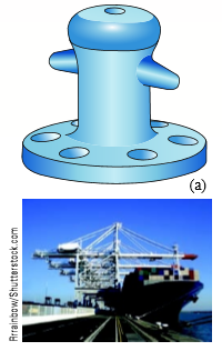
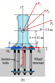
A cargo ship is tied down to marine bollards at a number of points along its length while its cargo is unloaded by a container handling crane. Each bollard is fastened to the wharf using anchor bolts. Three cables having known tension force magnitudes F1 = 110 kN, F2 = 85 kN, and F3 = 90 kN are secured to one bollard at a point A with coordinates (0, 0.45 m, 0) in the x-y-z coordinate system shown in the figure part b. Each cable force is directed at an attachment point on the ship. Force F1 is directed from point A to a point on the ship having coordinates (3 m, 9 m, 0); force F2 is directed at a point with coordinates (6.5 m, 8.5 m, 2 m); and force F3 is directed at a point with coordinates (8 m, 9 m, 5 m). The diameter of each anchor bolts is db = 24 mm.
(a) Find the reaction forces and reaction moments at the base of the bollard.
(b) Calculate the average shear stress in the anchor bolts (in the x-z plane). Assume each bolt carries an equal share of the total force.
Transcribed Image Text:
(a) Arrainbow/Shutterstock.com y (F2 F3 A Н-1.0 m S= 0.45 m a a Rx Anchor- Wharf bolts structure R. (b)
> Determine the allowable axial load Pallow for a W310 × 129 steel wide-flange column with pinned ends (see figure) for each of the following lengths: L = 3 m, 6 m, 9 m, and 12 m. (Assume E = 200 GPa and σY = 340 MPa.) A L A Se
> Segments AB and BCD of beam ABCD are pin connected at x 5 10 ft. The beam is supported by a pin support at A and roller supports at C and D; the roller at D is rotated by 308 from the x axis (see figure). A trapezoidal distributed load on BC varies in in
> Segments AB and BCD of beam ABCD are pin connected at x = 4 m. The beam is supported by a sliding support at A and roller supports at C and D (see figure). A triangularly distributed load with peak intensity of 80 N/m acts on BC. A concentrated moment is
> Segments AB and BC of beam ABC are pin connected a small distance to the right of joint B (see figure). Axial loads act at A and at the mid-span of AB. A concentrated moment is applied at joint B. (a) Find reactions at supports A, B, and C. (b) Find inte
> Find support reactions at A and B and then calculate the axial force N, shear force V, and bending moment M at mid-span of AB. Let L = 4 m, q0 = 160 N/m , P = 200 N, and Mo = 380 Nm?. Mo B L/2
> Find support reactions at A and B and then calculate the axial force N, shear force V, and bending moment M at mid-span of AB. Let L = 14 ft, qo 512 lb/ft, P = 50 lb, and M0 = 300 lb-ft. Mo 4 B 3 C L L/2 A
> Two separate cables AC and BC support a sign structure of weight W = 1575 lb attached to a building. The sign is also supported by a pin support at O and a lateral restraint in the z-direction at D. (a) Find the tension in each cable. Neglect the mass of
> A round bar ABC of length 2L (see figure) rotates about an axis through the midpoint C with constant angular speed ω (radians per second). The material of the bar has weight density g. (a) Derive a formula for the tensile stress x s in the bar
> Two gondolas on a ski lift are locked in the position show in the figure while repairs are being made elsewhere. The distance between support towers is L 5100 ft. The length of each cable segment under gondolas weighing WB = 450 lb and WC =650 lb are DAB
> A crane boom of mass 450 kg with its center of mass at C is stabilized by two cables AQ and BQ (Ae = 304 mm2 for each cable) as shown in the figure. A load P = 20 kN is supported at point D. The crane boom lies in the y-z plane. (a) Find the tension forc
> An L-shaped reinforced concrete slab 12 ft × 12 ft, with a 6 ft × 6 ft cut-out and thickness t = 9.0 in, is lifted by three cables attached at O, B, and D, as shown in the figure.
> A cable and pulley system at D is used to bring a 230-kg pole (ACB) to a vertical position, as shown in the figure part a. The cable has tensile force T and is attached at C. The length L of the pole is 6.0Â m, the outer diameter is d = 140 mm
> Solve the preceding problem if the mass of the tailgate is MT = 27 kg and that of the crate is MC = 68 kg. Use dimensions H = 305 mm, LÂ =Â 406Â mm, dCÂ =Â 460 mm, and dT = 350 mm. The cable cross-se
> A pickup truck tailgate supports a crate where WC = 150 lb, as shown in the figure. The tailgate weighs WT = 60 lb and is supported by two cables (only one is shown in the figure). Each cable has an effective cross-sectional area AE = 0.017 in2. (a) Find
> Two steel wires support a moveable overhead camera weighing W = 28 lb (see figure part a) used for close-up viewing of field action at sporting events. At some instant, wire 1 is at an angle a = 228 to the horizontal and wire 2 is at angle b = 408. Wires
> A circular aluminum tube with a length of L = 420 mm is loaded in compression by forces P (see figure). The hollow segment of length L/3 has outside and inside diameters of 60 mm and 35 mm, respectively. The solid segment of length 2L/3 has a diameter of
> A circular tube AB is fixed at one end and free at the other end. The tube is subjected to axial force at joint B. If the outer diameter of the tube is 3 in. and the thickness is ¾ in., calculate the maximum normal stress in the
> A square steel tube of a length L = 20 ft and width b2 = 10.0 in. is hoisted by a crane (see figure). The tube hangs from a pin of diameter d that is held by the cables at points A and B. The cross section is a hollow square with an inner dimension b1 =
> The data shown in the accompanying table are from a tensile test of high-strength steel. The test specimen has a diameter of 0.505 in. and a gage length of 2.00 in. At fracture, the elongation between the gage marks is 0.12Â in. and the minimu
> A specimen of a methacrylate plastic is tested in tension at room temperature (see figure), producing the stress-strain data listed in the accompanying table. Plot the stress-strain curve and determine the proportional limit, modulus of elasticity (which
> The strength-to-weight ratio of a structural material is defined as its load-carrying capacity divided by its weight. For materials in tension, use a characteristic tensile stress obtained from a stress strain curve as a measure of strength. For instance
> Three different materials, designated A, B, and C, are tested in tension using test specimens having diameters of 0.505 in. and gage lengths of 2.0 in. (see figure). At failure, the distances between the gage marks are found to be 2.13, 2.48, and 2.78 in
> A steel riser pipe hangs from a drill rig located offshore in deep water. (a) What is the greatest length (meters) it can have without breaking if the pipe is suspended in the air and the ultimate strength (or breaking strength) is 550 MPa? (b) If the sa
> A wire of length L = 4 ft and diameter d = 0.125 in. is stretched by tensile forces P = 600 lb. The wire is made of a copper alloy having a stress strain relationship that may be described mathematically by in which ε
> An aluminum bar has length L = 6 ft and diameter d = 1.375 in. The stress-strain curve for the aluminum is shown in Fig. 1-34. The initial straight line part of the curve has a slope (modulus of elasticity) of 10.61 063 psi. The bar is loaded
> A suspender on a suspension bridge consists of a cable that passes over the main cable (see figure) and supports the bridge deck, which is far below. The suspender is held in position by a metal tie that is prevented from sliding downward by clamps aroun
> A circular bar of magnesium alloy is 750 mm long. The stress-strain diagram for the material is shown in the figure. The bar is loaded in tension to an elongation of 6.0 mm, and then the load is removed. (a) What is the permanent set of the bar? (b) If t
> A bar made of structural steel having the stress-strain diagram shown in the figure has a length of 48 in. The yield stress of the steel is 42 ksi, and the slope of the initial linear part of the stress-strain curve (modulus of elasticity) is 30 Ã
> Three round, copper alloy bars having the same length L but different shapes are shown in the figure. The first bar has a diameter d over its entire length, the second has a diameter d over one-fifth of its length, and the third has a diameter d over one
> A hollow, brass circular pipe ABC (see figure) supports a load P1 = 26.5 kips acting at the top. A second load P2 = 22.0 kips is uniformly distributed around the cap plate at B. The diameters and thicknesses of the upper and lower parts of the pipe are d
> A tensile test is performed on a brass specimen 10 mm in diameter using a gage length of 50 mm (see figure). When the tensile load P reaches a value of 20 kN, the distance between the gage marks has increased by 0.122 mm. (a) What is the modulus of elast
> A bar of monel metal with a length LÂ = 9Â in. and a diameter d = 0.225 in. is loaded axially by a tensile force P (see figure). If the bar elongates by 0.0195 in., what is the decrease in diameter d? What is the magnitude of the lo
> A circular aluminum tube of length LÂ =Â 600Â mm is loaded in compression by forces P (see figure). The outside and inside diameters are d2 = 75 mm and d1 = 63 mm, respectively. A strain gage is placed on the outside of t
> A polyethylene bar having rectangular cross section with a width 7.35 in. and depth 7 in. is placed inside a hollow steel square section with side dimension of 8 in. The polyethylene bar is then compressed by an axial force P. At what value o
> Continuous cable ADB runs over a small frictionless pulley at D to support beam OABC that is part of an entrance canopy for a building (see figure). Assume that the canopy segment has a weight W = 1700 lb. (a) Find the required cross-sectional area of ca
> A round bar of 10 mm diameter is made of aluminum alloy 7075-T6 (see figure). When the bar is stretched by axial forces P, its diameter decreases by 0.016 mm. Find the magnitude of the load P. Obtain the material properties from Appendix I. |d= 10 m
> A bicycle chain consists of a series of small links, where each are 12 mm long between the centers of the pins (see figure). You might wish to examine a bicycle chain and observe its construction. Note particularly the pins, which have a diameter of 2.5
> A basketball player hangs on the rim after a dunk. He applies equal forces P1 = P2 = 110 lb at both A and B (see joint coordinates in the figure). Forces P1Â and P2 act parallel to the y-z plane. (a) Find the reactions at the support bracket (
> The top portion of a pole saw used to trim small branches from trees is shown in the figure part a. The cutting blade BCD (see figure parts a and c) applies a force P at point D. Ignore the effect of the weak return spring attached to the cut
> A shock mount constructed as shown in the figure is used to support a delicate instrument. The mount consists of an outer steel tube with inside diameter b, a central steel bar of diameter d that supports the load P, and a hollow rubber cylinder (height&
> Cable DB supports canopy beam OABC as shown in the figure. Find the required cross-sectional area of cable BD if the allowable normal stress is 125Â MPa. Determine the required diameter of the pins at O, B, and D if the allowable stress in she
> The clamp shown in the figure supports a load hanging from the lower flange of a steel beam. The clamp consists of two arms (A and B) joined by a pin at C. The pin has a diameter d = 12 mm. Because arm B straddles arm A, the pin is in double shear. Line
> A hitch-mounted bicycle rack is designed to carry up to four 30-lb bikes mounted on and strapped to two arms GH (see bike loads in the figure part a). The rack is attached to the vehicle at A and is assumed to be like a cantilever beam ABCDGH (figure par
> A flexible connection consisting of rubber pads (thickness t = 9 mm) bonded to steel plates is shown in the figure. The pads are 160 mm long and 80 mm wide. (a) Find the average shear strain aver g in the rubber if the force P = 16 kN and the shear modul
> A steel riser pipe hangs from a drill rig located offshore in deep water (see figure). Separate segments are joined using bolted flange plages (see figure part b and photo). Assume that there are six bolts at each pipe segment connection. Assume that the
> A punch for making a slotted hole in ID cards is shown in the figure part a. Assume that the hole produced by the punch can be described as a rectangle (12mm × 3 mm) with two half circles (r = 1 5 mm) on the left and the right si
> A joint between two glass plates A and B is filled with a flexible epoxy that bonds securely to the glass. The height of the joint is h = 0.5 in, its length is L = 30 in, and its thickness is t = 0.5 in. Shear force of V = 25 kips is applied to the joint
> A steel punch consists of two shafts: upper shaft and lower shaft. Assume that the upper shaft has a diameter d1 =24 mm and the bottom shaft has a diameter d2 = 16 mm. The punch is used to insert a hole in a 4 mm plate, as shown in the figure. If a force
> A joint between two concrete slabs A and B is filled with a flexible epoxy that bonds securely to the concrete (see figure). The height of the joint is h = 4.0in, its length is L = 40 in., and its thickness is t = 0.5 in. Under the action of shear forces
> An elastomeric bearing pad consisting of two steel plates bonded to a chloroprene elastomer (an artificial rubber) is subjected to a shear force V during a static loading test (see figure). The pad has dimensions a = 125 mm and b = 240 mm, and the elasto
> A special-purpose eye bolt with a shank diameter d = 0.50 in. passes through a hole in a steel plate of thickness tp = 0.75 in. (see figure) and is secured by a nut with thickness t = 0.25 in. The hexagonal nut bears directly against the steel plate. The
> A plane truss has joint loads P, P2, and P3 at joints D, C, and B, respectively (see figure) where load variable P = 5200 lb. All members have two end plates that are pin- connected to gusset plates. Each end plate has a thickness tp = 0.625 in, and all
> The inclined ladder AB supports a house painter (85 kg) at C and the weight (q = 4 0N/m) of the ladder itself. Each ladder rail (tr = 4 mm) is supported by a shoe (ts = 5 mm) that is attached to the ladder rail by a bolt of diameter dp = 8mm. Typica
> Truss members supporting a roof are connected to a 26-mm-thick gusset plate by a 22-mm diameter pin, as shown in the figure and photo. The two end plates on the truss members are each 14 mm thick. (a) If the load P = 80 kN, what is the largest bearing st
> The piston in an engine is attached to a connecting rod AB, which in turn is connected to a crank arm BC (see figure). The piston slides without friction in a cylinder and is subjected to a force P (assumed to be constant) while moving to the right in th
> A solid steel bar of a diameter d1 = 60 mm has a hole of a diameter d2 = 32 mm drilled through it (see figure). A steel pin of a diameter d2 passes through the hole and is attached to supports. Determine the maximum permissible tensile load Pallow in the
> A solid bar of circular cross section (diameter d) has a hole of diameter d/5 drilled laterally through the center of the bar (see figure). The allowable average tensile stress on the net cross section of the bar is sallow. (a) Obtain a formula for the a
> A plane truss is subjected to loads P2 and P at joints B and C, respectively, as shown in the figure part a. The truss bars are made of two L 102 × 76 × 6.4 steel angles having an ultimate stress in tensi
> A metal bar AB of a weight W is suspended by a system of steel wires arranged as shown in the figure. The diameter of the wires is 5/64 in., and the yield stress of the steel is 65 ksi. Determine the maximum permissible weight Wmax for a factor of safety
> What is the maximum possible value of the clamping force C in the jaws of the pliers shown in the figure if the ultimate shear stress in the 5-mm diameter pin is 340 MPa? What is the maximum permissible value of the applied load P to maintain a factor of
> A ship’s spar is attached at the base of a mast by a pin connection (see figure). The spar is a steel tube of outer diameter d2 = 3.5 in. and inner diameter d1 = 2.8 in. The steel pin has a diameter d = 1 in., and the two plates connect
> A cable and pulley system in the figure part a supports a cage of a mass 300 kg at B. Assume that this includes the mass of the cables as well. The thickness of each of the three steel pulleys is t = 40 mm. The pin diameters are dpA = 25 mm, dpB = 30 mm,
> A lifeboat hangs from two ship’s davits, as shown in the figure. A pin of diameter d = 0.80 in. passes through each davit and supports two pulleys, one on each side of the davit. Cables attached to the lifeboat pass over the pulleys and
> The rear hatch of a van (BDCG in figure part a) is supported by two hinges at B1 and B2 and by two struts A1B1 and A2B2 (diameter ds = 10 mm), as shown in figure part b. The struts are supported at A1 and A2 by pins, each with a diameter dp =
> A steel riser pipe hangs from a drill rig. Individual segments of equal length L = 50 ft are joined together using bolted flange plates (see figure part b). There are six bolts at each pipe segment connection. The outer and inner pipe diameters are d2 =
> A steel pad supporting heavy machinery rests on four short, hollow, cast iron piers (see figure). The ultimate strength of the cast iron in compression is 400 MPa. The total load P that may be supported by the pad is 900 kN. Using a factor of safety 3.0
> Two steel tubes are joined at B by four pins (dp = 1 1mm), as shown in the cross section a–a in the figure. The outer diameters of the tubes are dAB = 41 mmd and dBC = 28 mm. The wall thickness are tAB = 6.5mm and tBC = 7.5mm. The yield
> A tie-down on the deck of a sailboat consists of a bent bar bolted at both ends, as shown in the figure. The diameter dB of the bar is 1/4 in., the diameter dW of the washers is 7/8 in., and the thickness t of the fiberglass deck is 3/8 in. If the allowa
> A horizontal beam AB with cross-sectional dimensions (b = 0 .75 in.) × (h = 8.0in.) is supported by an inclined strut CD and carries a load P = 2700 lb at joint B (see figure part a). The strut, which consists of two bars each of thickness 5
> A torque To is transmitted between two flanged shafts by means of ten 20-mm bolts (see figure and photo). The diameter of the bolt circle is d = 250 mm. If the allowable shear stress in the bolts is 85 MPa, what is the maximum permissible torque? (Disreg
> Two bars AC and BC of the same material support a vertical load P (see figure). The length L of the horizontal bar is fixed, but the angle u can be varied by moving support A vertically and changing the length of bar AC to correspond with the new positio
> Continuous cable ADB runs over a small frictionless pulley at D to support beam OABC, which is part of an entrance canopy for a building (see figure). A downward distributed load with peak intensity qo = 5 kN/m at O acts on the beam (see figure). Assume
> Continuous cable ADB runs over a small frictionless pulley at D to support beam OABC, which is part of an entrance canopy for a building (see figure). The canopy segment has a weight W = 1700 lb that acts as a concentrated load in the middle of segment A
> A flat bar of a width 60 mm b 5 and thickness 10 mm t 5 is loaded in tension by a force P (see figure). The bar is attached to a support by a pin of a diameter d that passes through a hole of the same size in the bar. The allowable tensile stress on the
> An elevated jogging track is supported at intervals by a wood beam AB (L = 7 .5 ft) that is pinned at A and supported by steel rod BC and a steel washer at B. Both the rod (dBC = 3 /16 in.) and the washer (dB = 1 .0 in.) were designed using a rod tension
> A high-strength steel bar used in a large crane has a diameter d = 2.00 in. (see figure). The steel has a modulus of elasticity E = 29 × 106 psi and Poisson’s ratio is n = 0.29. Because of clearance requirements, the diamet
> Imagine that a long steel wire hangs vertically from a high-altitude balloon. (a) What is the greatest length (feet) it can have without yielding if the steel yields at 40 ksi? (b) If the same wire hangs from a ship at sea, what is the greatest length?
> A steel column of hollow circular cross section is supported on a circular, steel base plate and a concrete pedestal (see figure). The column has an outside diameter d = 250 mm and supports a load P = 750 kN. (a) If the allowable stress in the column is
> A hollow circular post ABC (see figure) supports a load P1 = 1700 lb acting at the top. A second load 2 P is uniformly distributed around the cap plate at B. The diameters and thicknesses of the upper and lower parts of the post are dab = 1.25 in, tab =
> A mountain bike is moving along a flat path at constant velocity. At some instant, the rider (weight = 670 N) applies pedal and hand forces, as shown in the figure part a. (a) Find reaction forces at the front and rear hubs. (Assume that the bike is pin
> An elliptical exerciser machine (see figure part a) is composed of front and back rails. A simplified plane-frame model of the back rail is shown in figure part b. Analyze the plane-frame model to find reaction forces at supports A, B, and C for the posi
> A soccer goal is subjected to gravity loads (in the 2z direction, w = 73 N/m for DG, BG, and BC; w = 29 N/m for all other members; see figure) and a force F = 200 N applied eccentrically at the mid-height of member DG. Find reactions at supports C, D, an
> Space frame ABC is clamped at A, except it is free to rotate at A about the x and y axes. Cables DC and EC support the frame at C. Force Py = 250lb is applied at the mid-span of AB, and a concentrated moment Mx = 220 in.-lb acts at joint B. (a) Find reac
> Space frame ABCD is clamped at A, except it is free to translate in the x direction. There is also a roller support at D, which is normal to line CDE. A triangularly distributed force with peak intensity qo = 75 N/m acts along AB in the positive z direct
> A special vehicle brake is clamped at O when the brake force 1 P is applied (see figure). Force P1 = 50lb and lies in a plane that is parallel to the x-z plane and is applied at C normal to line BC. Force P2 = 40 lb and is applied at B in the 2y directio
> A plane frame has a pin support at A and roller supports at C and E (see figure). Frame segments ABD and CDEF are joined just left of joint D by a pin connection. (a) Find reactions at supports A, C, and E. (b) Find the resultant force in the pin just le
> A 150-lb rigid bar AB, with frictionless rollers at each end, is held in the position shown in the figure by a continuous cable CAD. The cable is pinned at C and D and runs over a pulley at A. (a) Find reactions at supports A and B. (b) Find the force in
> A plane frame with a pin support at A and roller supports at C and E has a cable attached at E, which runs over frictionless pulleys at D and B (see figure). The cable force is known to be 400 N. There is a pin connection just to the left of joint C. (a)
> A large precast concrete panel for a warehouse is raised using two sets of cables at two lift lines, as shown in the figure part a. Cable 1 has a length L1 = 22 ft, cable 2 has a length L2 = 10 ft, and the distance along the panel between lift points B a
> A plane frame with pin supports at A and E has a cable attached at C, which runs over a frictionless pulley at F (see figure). The cable force is known to be 500 lb. (a) Find reactions at supports A and E. (b) Find internal stress resultants N, V, and M
> A plane frame is constructed by using a pin connection between segments ABC and CDE. The frame has pin supports at A and E and joint loads at B and D (see figure). (a) Find reactions at supports A and E. (b) Find the resultant force in the pin at C.
> A 200-lb trap door (AB) is supported by a strut (BC) which is pin connected to the door at B (see figure). (a) Find reactions at supports A and C. (b) Find internal stress resultants N, V, and M on the trap door at 20 in. from A. B Pin or hinge conn
> Find support reactions at A and D and then calculate the axial force N, shear force V, and bending moment M at mid-span of column BD. Let L = 4 m, qo = 160 N/m, P 5 200 N, and Mo = 380 Nm? Mo 4 4 L/2 3 B 3 L L/2 y D
> A plane frame is restrained at joints A and D, as shown in the figure. Members AB and BCD are pin connected at B. A triangularly distributed lateral load with peak intensity of 80 N/m acts on CD. An inclined concentrated force of 200 N acts at the mid-sp
> A stepped shaft ABC consisting of two solid, circular segments is subjected to uniformly distributed torque t1 acting over segment 1 and concentrated torque T2 applied at C, as shown in the figure. Segment 1 of the shaft has a diameter of d1 = 57 mm and
> A stepped shaft ABC consisting of two solid, circular segments is subjected to torques T1 and T2 acting in opposite directions, as shown in the figure. The larger segment of the shaft has a diameter of d1 = 2.25 in. and a length L1 = 30 in.; the smaller
> A space truss is restrained at joints A, B, and C, as shown in the figure. Load P acts in the 1z direction at joint B and in the 2z directions at joint C. Coordinates of all joints are given in terms of dimension variable L (see figure). Let P = 5 kN and
> A tubular post of outer diameter d2 is guyed by two cables fitted with turnbuckles (see figure). The cables are tightened by rotating the turnbuckles, producing tension in the cables and compression in the post. Both cables are tightened to a tensile for
> A space truss is restrained at joints A, B, and C, as shown in the figure. Load 2P is applied at in the 2x direction at joint A, load 3P acts in the 1z direction at joint B, and load P is applied in the 1z direction at joint C. Coordinates of all joints
> A space truss is restrained at joints O, A, B, and C, as shown in the figure. Load P is applied at joint A and load 2P acts downward at joint C. (a) Find reaction force components Ax, By, and Bz in terms of load variable P. (b) Find the axial force in tr

