Question: A stepped shaft ABC consisting of two
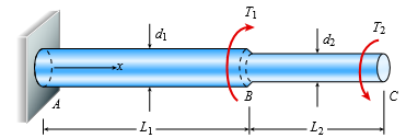
A stepped shaft ABC consisting of two solid, circular segments is subjected to torques T1 and T2 acting in opposite directions, as shown in the figure. The larger segment of the shaft has a diameter of d1 = 2.25 in. and a length L1 = 30 in.; the smaller segment has a diameter d2 = 1.75 in. and a length L2 = 20 in. The torques are T1 = 21,000 lb-in. and T2 = 10,000 lb-in.
(a) Find reaction torque TA at support A.
(b) Find the internal torque T(x) at two locations: x = L1 /2 and x = L1 1 L2/2. Show these internal torques on properly drawn free-body diagrams (FBDs).
Transcribed Image Text:
di B L2
> A solid steel bar of a diameter d1 = 60 mm has a hole of a diameter d2 = 32 mm drilled through it (see figure). A steel pin of a diameter d2 passes through the hole and is attached to supports. Determine the maximum permissible tensile load Pallow in the
> A solid bar of circular cross section (diameter d) has a hole of diameter d/5 drilled laterally through the center of the bar (see figure). The allowable average tensile stress on the net cross section of the bar is sallow. (a) Obtain a formula for the a
> A plane truss is subjected to loads P2 and P at joints B and C, respectively, as shown in the figure part a. The truss bars are made of two L 102 × 76 × 6.4 steel angles having an ultimate stress in tensi
> A metal bar AB of a weight W is suspended by a system of steel wires arranged as shown in the figure. The diameter of the wires is 5/64 in., and the yield stress of the steel is 65 ksi. Determine the maximum permissible weight Wmax for a factor of safety
> What is the maximum possible value of the clamping force C in the jaws of the pliers shown in the figure if the ultimate shear stress in the 5-mm diameter pin is 340 MPa? What is the maximum permissible value of the applied load P to maintain a factor of
> A ship’s spar is attached at the base of a mast by a pin connection (see figure). The spar is a steel tube of outer diameter d2 = 3.5 in. and inner diameter d1 = 2.8 in. The steel pin has a diameter d = 1 in., and the two plates connect
> A cable and pulley system in the figure part a supports a cage of a mass 300 kg at B. Assume that this includes the mass of the cables as well. The thickness of each of the three steel pulleys is t = 40 mm. The pin diameters are dpA = 25 mm, dpB = 30 mm,
> A lifeboat hangs from two ship’s davits, as shown in the figure. A pin of diameter d = 0.80 in. passes through each davit and supports two pulleys, one on each side of the davit. Cables attached to the lifeboat pass over the pulleys and
> The rear hatch of a van (BDCG in figure part a) is supported by two hinges at B1 and B2 and by two struts A1B1 and A2B2 (diameter ds = 10 mm), as shown in figure part b. The struts are supported at A1 and A2 by pins, each with a diameter dp =
> A steel riser pipe hangs from a drill rig. Individual segments of equal length L = 50 ft are joined together using bolted flange plates (see figure part b). There are six bolts at each pipe segment connection. The outer and inner pipe diameters are d2 =
> A steel pad supporting heavy machinery rests on four short, hollow, cast iron piers (see figure). The ultimate strength of the cast iron in compression is 400 MPa. The total load P that may be supported by the pad is 900 kN. Using a factor of safety 3.0
> Two steel tubes are joined at B by four pins (dp = 1 1mm), as shown in the cross section a–a in the figure. The outer diameters of the tubes are dAB = 41 mmd and dBC = 28 mm. The wall thickness are tAB = 6.5mm and tBC = 7.5mm. The yield
> A tie-down on the deck of a sailboat consists of a bent bar bolted at both ends, as shown in the figure. The diameter dB of the bar is 1/4 in., the diameter dW of the washers is 7/8 in., and the thickness t of the fiberglass deck is 3/8 in. If the allowa
> A horizontal beam AB with cross-sectional dimensions (b = 0 .75 in.) × (h = 8.0in.) is supported by an inclined strut CD and carries a load P = 2700 lb at joint B (see figure part a). The strut, which consists of two bars each of thickness 5
> A torque To is transmitted between two flanged shafts by means of ten 20-mm bolts (see figure and photo). The diameter of the bolt circle is d = 250 mm. If the allowable shear stress in the bolts is 85 MPa, what is the maximum permissible torque? (Disreg
> Two bars AC and BC of the same material support a vertical load P (see figure). The length L of the horizontal bar is fixed, but the angle u can be varied by moving support A vertically and changing the length of bar AC to correspond with the new positio
> Continuous cable ADB runs over a small frictionless pulley at D to support beam OABC, which is part of an entrance canopy for a building (see figure). A downward distributed load with peak intensity qo = 5 kN/m at O acts on the beam (see figure). Assume
> Continuous cable ADB runs over a small frictionless pulley at D to support beam OABC, which is part of an entrance canopy for a building (see figure). The canopy segment has a weight W = 1700 lb that acts as a concentrated load in the middle of segment A
> A flat bar of a width 60 mm b 5 and thickness 10 mm t 5 is loaded in tension by a force P (see figure). The bar is attached to a support by a pin of a diameter d that passes through a hole of the same size in the bar. The allowable tensile stress on the
> An elevated jogging track is supported at intervals by a wood beam AB (L = 7 .5 ft) that is pinned at A and supported by steel rod BC and a steel washer at B. Both the rod (dBC = 3 /16 in.) and the washer (dB = 1 .0 in.) were designed using a rod tension
> A high-strength steel bar used in a large crane has a diameter d = 2.00 in. (see figure). The steel has a modulus of elasticity E = 29 × 106 psi and Poisson’s ratio is n = 0.29. Because of clearance requirements, the diamet
> Imagine that a long steel wire hangs vertically from a high-altitude balloon. (a) What is the greatest length (feet) it can have without yielding if the steel yields at 40 ksi? (b) If the same wire hangs from a ship at sea, what is the greatest length?
> A steel column of hollow circular cross section is supported on a circular, steel base plate and a concrete pedestal (see figure). The column has an outside diameter d = 250 mm and supports a load P = 750 kN. (a) If the allowable stress in the column is
> A hollow circular post ABC (see figure) supports a load P1 = 1700 lb acting at the top. A second load 2 P is uniformly distributed around the cap plate at B. The diameters and thicknesses of the upper and lower parts of the post are dab = 1.25 in, tab =
> A mountain bike is moving along a flat path at constant velocity. At some instant, the rider (weight = 670 N) applies pedal and hand forces, as shown in the figure part a. (a) Find reaction forces at the front and rear hubs. (Assume that the bike is pin
> An elliptical exerciser machine (see figure part a) is composed of front and back rails. A simplified plane-frame model of the back rail is shown in figure part b. Analyze the plane-frame model to find reaction forces at supports A, B, and C for the posi
> A soccer goal is subjected to gravity loads (in the 2z direction, w = 73 N/m for DG, BG, and BC; w = 29 N/m for all other members; see figure) and a force F = 200 N applied eccentrically at the mid-height of member DG. Find reactions at supports C, D, an
> Space frame ABC is clamped at A, except it is free to rotate at A about the x and y axes. Cables DC and EC support the frame at C. Force Py = 250lb is applied at the mid-span of AB, and a concentrated moment Mx = 220 in.-lb acts at joint B. (a) Find reac
> Space frame ABCD is clamped at A, except it is free to translate in the x direction. There is also a roller support at D, which is normal to line CDE. A triangularly distributed force with peak intensity qo = 75 N/m acts along AB in the positive z direct
> A special vehicle brake is clamped at O when the brake force 1 P is applied (see figure). Force P1 = 50lb and lies in a plane that is parallel to the x-z plane and is applied at C normal to line BC. Force P2 = 40 lb and is applied at B in the 2y directio
> A plane frame has a pin support at A and roller supports at C and E (see figure). Frame segments ABD and CDEF are joined just left of joint D by a pin connection. (a) Find reactions at supports A, C, and E. (b) Find the resultant force in the pin just le
> A 150-lb rigid bar AB, with frictionless rollers at each end, is held in the position shown in the figure by a continuous cable CAD. The cable is pinned at C and D and runs over a pulley at A. (a) Find reactions at supports A and B. (b) Find the force in
> A plane frame with a pin support at A and roller supports at C and E has a cable attached at E, which runs over frictionless pulleys at D and B (see figure). The cable force is known to be 400 N. There is a pin connection just to the left of joint C. (a)
> A large precast concrete panel for a warehouse is raised using two sets of cables at two lift lines, as shown in the figure part a. Cable 1 has a length L1 = 22 ft, cable 2 has a length L2 = 10 ft, and the distance along the panel between lift points B a
> A plane frame with pin supports at A and E has a cable attached at C, which runs over a frictionless pulley at F (see figure). The cable force is known to be 500 lb. (a) Find reactions at supports A and E. (b) Find internal stress resultants N, V, and M
> A plane frame is constructed by using a pin connection between segments ABC and CDE. The frame has pin supports at A and E and joint loads at B and D (see figure). (a) Find reactions at supports A and E. (b) Find the resultant force in the pin at C.
> A 200-lb trap door (AB) is supported by a strut (BC) which is pin connected to the door at B (see figure). (a) Find reactions at supports A and C. (b) Find internal stress resultants N, V, and M on the trap door at 20 in. from A. B Pin or hinge conn
> Find support reactions at A and D and then calculate the axial force N, shear force V, and bending moment M at mid-span of column BD. Let L = 4 m, qo = 160 N/m, P 5 200 N, and Mo = 380 Nm? Mo 4 4 L/2 3 B 3 L L/2 y D
> A plane frame is restrained at joints A and D, as shown in the figure. Members AB and BCD are pin connected at B. A triangularly distributed lateral load with peak intensity of 80 N/m acts on CD. An inclined concentrated force of 200 N acts at the mid-sp
> A stepped shaft ABC consisting of two solid, circular segments is subjected to uniformly distributed torque t1 acting over segment 1 and concentrated torque T2 applied at C, as shown in the figure. Segment 1 of the shaft has a diameter of d1 = 57 mm and
> A space truss is restrained at joints A, B, and C, as shown in the figure. Load P acts in the 1z direction at joint B and in the 2z directions at joint C. Coordinates of all joints are given in terms of dimension variable L (see figure). Let P = 5 kN and
> A tubular post of outer diameter d2 is guyed by two cables fitted with turnbuckles (see figure). The cables are tightened by rotating the turnbuckles, producing tension in the cables and compression in the post. Both cables are tightened to a tensile for
> A space truss is restrained at joints A, B, and C, as shown in the figure. Load 2P is applied at in the 2x direction at joint A, load 3P acts in the 1z direction at joint B, and load P is applied in the 1z direction at joint C. Coordinates of all joints
> A space truss is restrained at joints O, A, B, and C, as shown in the figure. Load P is applied at joint A and load 2P acts downward at joint C. (a) Find reaction force components Ax, By, and Bz in terms of load variable P. (b) Find the axial force in tr
> A space truss has three-dimensional pin supports at joints O, B, and C. Load P is applied at joint A and acts toward point Q. Coordinates of all joints are given in feet (see figure). (a) Find reaction force components Bx, Bz, and Oz. (b) Find the axial
> Repeat 1.3-10 but use the method of sections to find member forces in AB and DC. Data from Problem 10: Find support reactions at A and B and then use the method of joints to find all member forces. Let b = 3 m and P = 80 kN. y 2P b/2 2
> Repeat 1.3-9 but use the method of sections to find member forces in AC and BD. Data from Problem 9: Find support reactions at A and B and then use the method of joints to find all member forces. Let c = 8 ft and P = 20 kips. -2P -Oc = 80° a O3 =
> A plane truss has a pin support at F and a roller support at D (see figure). (a) Find reactions at both supports. (b) Find the axial force in truss member FE. 16 kN 19 kN 3 m 13 kN A 3 m B 3 m D 3 m E 4.5 m f1 m
> A plane truss has a pin support at A and a roller support at E (see figure). (a) Find reactions at all supports. (b) Find the axial force in truss member FE. |3 kips 2 kips 10 ft D 1 kips A 10 ft B 10 ft C 10 ft 15 ft 3 ft G
> Consider the plane truss with a pin support at joint 3 and a vertical roller support at joint 5 (see figure). (a) Find reactions at support joints 3 and 5. (b) Find axial forces in truss members 11 and 13. 20 N 45 N 4 5 6 6. 7 12 11 7 10) 2 m 13 9 6
> A pressurized circular cylinder has a sealed cover plate fastened with steel bolts (see figure). The pressure p of the gas in the cylinder is 290 psi, the inside diameter D of the cylinder is 10.0 in., and the diameter dB of the b
> The torsional pendulum shown in the figure consists of a horizontal circular disk of a mass M = 60 kg suspended by a vertical steel wire (G = 8 0GPa) of a length L = 2 m and diameter d = 4 mm. Calculate the maximum permissible angle of rotation â&#
> A W 12 × 35 steel cantilever beam is subjected to an axial load P = 10 kips and a transverse load V = 15 kips. The beam has length L = 6 ft. (a) Calculate the principal normal stresses and the maximum shear stress for an element located at C
> A wood beam with a cross section 4 × 6 in. is simply supported at A and B. The beam has a length of 9 ft and is subjected to point load P = 5 kips at mid-span. Calculate the state of stress at point C located 4 in. below the top of the beam
> A fire extinguisher tank is designed for an internal pressure of 825 psi. The tank has an outer diameter of 4.5 in. and thickness of 0.08 in. Calculate the longitudinal stress, the circumferential stress, and the maximum shear stresses (out-of-plane and
> A spherical balloon is filled with a gas. The outer diameter of the balloon is 20 in. and the thickness is 0.012 in. Calculate the maximum permissible pressure in the balloon if the allowable tensile stress and the allowable shear stress in the balloon a
> A hollow, pressurized sphere having a radius r = 4.8 in. and wall thickness t = 0.4in. is lowered into a lake (see figure). The compressed air in the tank is at a pressure of 24 psi (gage pressure when the tank is out of the water). At what depth D0 will
> Solve the preceding problem if the diameter is 480 mm, the pressure is 20 MPa, the yield stress in tension is 975 MPa, the yield stress in shear is 460 MPa, the factor of safety is 2.75, the modulus of elasticity is 210 GPa, Poisson’s ratio is 0.28, and
> A cylindrical pressure vessel with flat ends is subjected to a torque T and a bending moment M (see figure). The outer radius is 12.0 in. and the wall thickness is 1.0 in. The loads are T = 800 kip-in, M = 1000 kip-in, and the internal pressure p = 900 p
> A spherical stainless-steel tank having a diameter of 26 in. is used to store propane gas at a pressure of 2075 psi. The properties of the steel are as follows: yield stress in tension, 140,000 psi; yield stress in shear, 65,000 psi; modulus of elasticit
> Solve the preceding problem for the following data: diameter 1.0 m, thickness 48 mm, pressure 22 MPa, modulus 210 GPa, and Poisson’s ratio 0.29. Data from Problem 9: A spherical tank of diameter 48 in. and wall thickness 1.75 in. con
> A spherical tank of diameter 48 in. and wall thickness 1.75 in. contains compressed air at a pressure of 2200 psi. The tank is constructed of two hemispheres joined by a welded seam (see figure). (a) What is the tensile load f (lb per in. of length of we
> A spherical steel pressure vessel (diameter 500 mm, thickness 10 mm) is coated with brittle lacquer that cracks when the strain reaches 150 × 1026 (see figure). (a) What internal pressure p will cause the lacquer to develop cracks? (Assume E
> (a) Solve part (a) of the preceding problem if the pressure is 8.5 psi, the diameter is 10 in., the wall thickness is 0.05 in., the modulus of elasticity is 200 psi, and Poisson’s ratio is 0.48. (b) If the strain must be lim
> A rubber ball (see figure) is inflated to a pressure of 65 kPa. At that pressure, the diameter of the ball is 240 mm and the wall thickness is 1.25 mm. The rubber has a modulus of elasticity E = 3.7 MPa and Poisson’s ratio v = 0.48. (a)
> A hemispherical window (or viewport) in a decompression chamber (see figure) is subjected to an internal air pressure of 85 psi. The window is attached to the wall of the chamber by 14 bolts. (a) Find the tensile force F in each bolt and the tensile stre
> Solve the preceding problem if the internal pressure is 3.85 MPa, the diameter is 20 m, the yield stress is 590 MPa, and the factor of safety is 3.0. (a) Determine the required thickness to the nearest millimeter. (b) If the tank wall thickness is 85 mm,
> A large spherical tank (see figure) contains gas at a pressure of 420 psi. The tank is 45 ft in diameter and is constructed of high-strength steel having a yield stress in tension of 80 ksi. (a) Determine the required thickness (to the nearest 1/4 inch)
> A spherical balloon with an outer diameter of 500 mm and thickness 0.3 mm is filled with a gas. Calculate maximum permissible pressure in the balloon if the allowable normal strain at the outer surface of the balloon is 0.1. Assume E = 4 MPa and v = 0.45
> A pressurized cylindrical tank with flat ends is loaded by torques T and tensile forces P (see figure). The tank has a radius of r = 125 mm and wall thickness t = 6.5 mm. The internal pressure p = 7.25 MPa and the torque T = 850 Nm. (a) What is the maxim
> A cylindrical tank with diameter d = 18 in. is subjected to internal gas pressure p = 450 psi. The tank is constructed of steel sections that are welded circumferentially (see figure). The heads of the tank are hemispherical. The allowable tensile and sh
> A cylindrical tank with hemispherical heads is constructed of steel sections that are welded circumferentially (see figure). The tank diameter is 1.25 m, the wall thickness is 22 mm, and the internal pressure is 1750 kPa. (a) Determine the maximum tensil
> A standpipe in a water-supply system (see figure) is 12 ft in diameter and 6 in. thick. Two horizontal pipes carry water out of the standpipe; each is 2 ft in diameter and 1 in. thick. When the system is shut down and water fills the pipes but is not mov
> Solve the preceding problem if d = 90 mm, F = 42 kN, and τallow = 40 MPa. Data from Problem 9: A cylinder filled with oil is under pressure from a piston, as shown in the figure. The diameter d of the piston is 1.80 in. and the
> A cylinder filled with oil is under pressure from a piston, as shown in the figure. The diameter d of the piston is 1.80 in. and the compressive force F is 3500 lb. The maximum allowable shear stress tallow in the wall of the cylinder is 5500
> A circular cylindrical steel tank (see figure) contains a volatile fuel under pressure. A strain gage at point A records the longitudinal strain in the tank and transmits this information to a control room. The ultimate shear stress in the wall of the ta
> A strain gage is installed in the longitudinal direction on the surface of an aluminum beverage can (see figure). The radius-to-thickness ratio of the can is 200. When the lid of the can is popped open, the strain changes by ε0 = 187 Ã
> A thin-walled cylindrical pressure vessel of a radius r is subjected simultaneously to internal gas pressure p and a compressive force F acting at the ends (see figure). (a) What should be the magnitude of the force F in order to produce pure shear in th
> A cylindrical pressure vessel having a radius r = 14 in. and wall thickness t = 0.5 in. is subjected to internal pressure p = 375 psi. In addition, a torque T = 90 kip-ft acts at each end of the cylinder (see figure). (a) Determine the maximum tensile st
> An inflatable structure used by a traveling circus has the shape of a half-circular cylinder with closed ends (see figure). The fabric and plastic structure is inflated by a small blower and has a radius of 40 ft when fully inflated. A longitudinal seam
> A tall standpipe with an open top (see figure) has diameter d = 2.2m and wall thickness t = 20 mm. (a) What height h of water will produce a circumferential stress of 12 MPa in the wall of the standpipe? (b) What is the axial stress in the wall of the ta
> A scuba tank (see figure) is being designed for an internal pressure of 2640 psi with a factor of safety of 2.0 with respect to yielding. The yield stress of the steel is 65,000 psi in tension and 32,000 psi in shear. (a) If the diameter of the tank is 7
> Repeat Problem 1 for a fire extinguisher tank with an internal pressure of 1.8 MPa, diameter of 130 mm, and thickness 1.5 mm. Data from Problem 1: A fire extinguisher tank is designed for an internal pressure of 825 psi. The tank has an outer diameter
> Solve the preceding problem using the numerical data: b = 90 mm, h = 280 mm, d = 210 mm, q = 14 kN/m, and L = 1.2 m. Data from Problem 21: Beam ABCD has a sliding support at A, roller supports at C and D, and a pin connection at B (see figure). Assume
> Beam ABCD has a sliding support at A, roller supports at C and D, and a pin connection at B (see figure). Assume that the beam has a rectangular cross section (b = 4 in., h = 12 in.). Uniform load q acts on ABC and a concentrated moment is applied at D.
> A cantilever beam with a T-section is loaded by an inclined force of magnitude 6.5 kN (see figure). The line of action of the force is inclined at an angle of 8 60 to the horizontal and intersects the top of the beam at the end cross section. The beam is
> A W 12 × 14 wide-flange beam is simply supported with a span length of 120 in. (see figure). The beam supports two anti-symmetrically placed concentrated loads of 7.5 kips each. At a cross section located 20 in. from the right ha
> A W 360 × 79 steel beam is fixed at A. The beam has a length of 2.5 m and is subjected to a linearly varying distributed load with maximum intensity qo = 500 N/m on segment AB and a uniformly distributed load of intensity q0 on segment BC. C
> A W 12 × 35 steel beam is fixed at A. The beam has length L = 6 ft and is subjected to a linearly varying distributed load with peak intensity qo = 830 lb/ft. Calculate the state of plane stress at point C located 3 in. below the top of the
> A W 200 × 41.7 wide-flange beam is simply supported with a span length of 2.5 m (see figure). The beam supports a concentrated load of 100 kN at 0.9 m from support B. At a cross section located 0.7 m from the left-hand support, determine the
> A beam with a wide-flange cross section (see figure) has the following dimensions: b = 5 in., t = 0.5 in., h = 12 in., and h1 = 10.5 in. The beam is simply supported with span length L = 10 ft and supports a uniform load q = 6 kips/ft. Calculate the prin
> A beam with a wide-flange cross section (see figure) has the following dimensions: b = 120 mm, t = 10 mm, h = 300 mm, and h1 = 260 mm. The beam is simply supported with span length L = 3.0m. AÂ concentrated load P = 120 kN acts at the midpoint
> A cantilever beam (width b = 3 in. and depth h = 6 in.) has a length L = 5 ft and is subjected to a point load P and a concentrated moment M = 20 kip-ft at end B. If normal stress σx = 0 at point C, located 0.5 in. below the top of the beam an
> A cantilever wood beam with a width b = 100 mm and depth h = 150 mm has a length L = 2 m and is subjected to point load P at mid-span and uniform load q = 15 N/m. (a) If the normal stress σx = 0 at point C, located 120 mm below the top of the
> Solve the preceding problem if the stress and dimensions are σ1 = 2450 psi, L = 80 in., b = 2.5 in., h = 10 in., and d = 2.5 in. Data from Problem 10: An overhanging beam ABC has a guided support at A, a rectangular cross section, and suppo
> An overhanging beam ABC has a guided support at A, a rectangular cross section, and supports an upward uniform load q = P/L over AB and a downward concentrated load P at the free end C (see figure). The span length from A to B is L, and the length of the
> A simple beam with a rectangular cross section (width, 3.5 in.; height, 12 in.) carries a trapezoid ally distributed load of 1400 lb/ft at A and 1000 lb/ft at B on a span of 14 ft (see figure). Find the principal stresses σ1 and σ2
> Solve the preceding problem for the following data: P = 160 kN, N = 200 kN, L = 2 m, b = 95 mm, h = 300 mm, and d = 200 mm. Data from Problem 7: A cantilever beam (L = 6 ft) with a rectangular cross section (b = 3.5 in., h = 12 in.) supports an upward
> A cantilever beam (L = 6 ft) with a rectangular cross section (b = 3.5 in., h = 12 in.) supports an upward load P = 35 kips at its free end. (a) Find the state of stress (σx, σy, and τxy in ksi) on a plane-stress element
> A cylindrical tank having a diameter d = 2.5 in. is subjected to internal gas pressure p = 600 psi and an external tensile load T = 1000 lb (see figure). Determine the minimum thickness t of the wall of the tank based upon an allowable shear stress of 30

