Question: A W 360 × 79 steel beam is
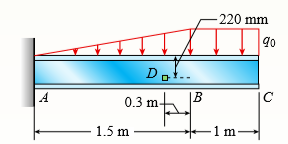
A W 360 × 79 steel beam is fixed at A. The beam has a length of 2.5 m and is subjected to a linearly varying distributed load with maximum intensity qo = 500 N/m on segment AB and a uniformly distributed load of intensity q0 on segment BC. Calculate the state of plane stress at point D located 220 mm below the top of the beam and 0.3 m to the left of point B. Find the principal normal stresses and the maximum shear stress at D. Include the weight of the beam.
Transcribed Image Text:
- 220 mm Dot.. C A 0.3 m 1.5 m -1 m-
> A tubular post of outer diameter d2 is guyed by two cables fitted with turnbuckles (see figure). The cables are tightened by rotating the turnbuckles, producing tension in the cables and compression in the post. Both cables are tightened to a tensile for
> A space truss is restrained at joints A, B, and C, as shown in the figure. Load 2P is applied at in the 2x direction at joint A, load 3P acts in the 1z direction at joint B, and load P is applied in the 1z direction at joint C. Coordinates of all joints
> A space truss is restrained at joints O, A, B, and C, as shown in the figure. Load P is applied at joint A and load 2P acts downward at joint C. (a) Find reaction force components Ax, By, and Bz in terms of load variable P. (b) Find the axial force in tr
> A space truss has three-dimensional pin supports at joints O, B, and C. Load P is applied at joint A and acts toward point Q. Coordinates of all joints are given in feet (see figure). (a) Find reaction force components Bx, Bz, and Oz. (b) Find the axial
> Repeat 1.3-10 but use the method of sections to find member forces in AB and DC. Data from Problem 10: Find support reactions at A and B and then use the method of joints to find all member forces. Let b = 3 m and P = 80 kN. y 2P b/2 2
> Repeat 1.3-9 but use the method of sections to find member forces in AC and BD. Data from Problem 9: Find support reactions at A and B and then use the method of joints to find all member forces. Let c = 8 ft and P = 20 kips. -2P -Oc = 80° a O3 =
> A plane truss has a pin support at F and a roller support at D (see figure). (a) Find reactions at both supports. (b) Find the axial force in truss member FE. 16 kN 19 kN 3 m 13 kN A 3 m B 3 m D 3 m E 4.5 m f1 m
> A plane truss has a pin support at A and a roller support at E (see figure). (a) Find reactions at all supports. (b) Find the axial force in truss member FE. |3 kips 2 kips 10 ft D 1 kips A 10 ft B 10 ft C 10 ft 15 ft 3 ft G
> Consider the plane truss with a pin support at joint 3 and a vertical roller support at joint 5 (see figure). (a) Find reactions at support joints 3 and 5. (b) Find axial forces in truss members 11 and 13. 20 N 45 N 4 5 6 6. 7 12 11 7 10) 2 m 13 9 6
> A pressurized circular cylinder has a sealed cover plate fastened with steel bolts (see figure). The pressure p of the gas in the cylinder is 290 psi, the inside diameter D of the cylinder is 10.0 in., and the diameter dB of the b
> The torsional pendulum shown in the figure consists of a horizontal circular disk of a mass M = 60 kg suspended by a vertical steel wire (G = 8 0GPa) of a length L = 2 m and diameter d = 4 mm. Calculate the maximum permissible angle of rotation â&#
> A W 12 × 35 steel cantilever beam is subjected to an axial load P = 10 kips and a transverse load V = 15 kips. The beam has length L = 6 ft. (a) Calculate the principal normal stresses and the maximum shear stress for an element located at C
> A wood beam with a cross section 4 × 6 in. is simply supported at A and B. The beam has a length of 9 ft and is subjected to point load P = 5 kips at mid-span. Calculate the state of stress at point C located 4 in. below the top of the beam
> A fire extinguisher tank is designed for an internal pressure of 825 psi. The tank has an outer diameter of 4.5 in. and thickness of 0.08 in. Calculate the longitudinal stress, the circumferential stress, and the maximum shear stresses (out-of-plane and
> A spherical balloon is filled with a gas. The outer diameter of the balloon is 20 in. and the thickness is 0.012 in. Calculate the maximum permissible pressure in the balloon if the allowable tensile stress and the allowable shear stress in the balloon a
> A hollow, pressurized sphere having a radius r = 4.8 in. and wall thickness t = 0.4in. is lowered into a lake (see figure). The compressed air in the tank is at a pressure of 24 psi (gage pressure when the tank is out of the water). At what depth D0 will
> Solve the preceding problem if the diameter is 480 mm, the pressure is 20 MPa, the yield stress in tension is 975 MPa, the yield stress in shear is 460 MPa, the factor of safety is 2.75, the modulus of elasticity is 210 GPa, Poisson’s ratio is 0.28, and
> A cylindrical pressure vessel with flat ends is subjected to a torque T and a bending moment M (see figure). The outer radius is 12.0 in. and the wall thickness is 1.0 in. The loads are T = 800 kip-in, M = 1000 kip-in, and the internal pressure p = 900 p
> A spherical stainless-steel tank having a diameter of 26 in. is used to store propane gas at a pressure of 2075 psi. The properties of the steel are as follows: yield stress in tension, 140,000 psi; yield stress in shear, 65,000 psi; modulus of elasticit
> Solve the preceding problem for the following data: diameter 1.0 m, thickness 48 mm, pressure 22 MPa, modulus 210 GPa, and Poisson’s ratio 0.29. Data from Problem 9: A spherical tank of diameter 48 in. and wall thickness 1.75 in. con
> A spherical tank of diameter 48 in. and wall thickness 1.75 in. contains compressed air at a pressure of 2200 psi. The tank is constructed of two hemispheres joined by a welded seam (see figure). (a) What is the tensile load f (lb per in. of length of we
> A spherical steel pressure vessel (diameter 500 mm, thickness 10 mm) is coated with brittle lacquer that cracks when the strain reaches 150 × 1026 (see figure). (a) What internal pressure p will cause the lacquer to develop cracks? (Assume E
> (a) Solve part (a) of the preceding problem if the pressure is 8.5 psi, the diameter is 10 in., the wall thickness is 0.05 in., the modulus of elasticity is 200 psi, and Poisson’s ratio is 0.48. (b) If the strain must be lim
> A rubber ball (see figure) is inflated to a pressure of 65 kPa. At that pressure, the diameter of the ball is 240 mm and the wall thickness is 1.25 mm. The rubber has a modulus of elasticity E = 3.7 MPa and Poisson’s ratio v = 0.48. (a)
> A hemispherical window (or viewport) in a decompression chamber (see figure) is subjected to an internal air pressure of 85 psi. The window is attached to the wall of the chamber by 14 bolts. (a) Find the tensile force F in each bolt and the tensile stre
> Solve the preceding problem if the internal pressure is 3.85 MPa, the diameter is 20 m, the yield stress is 590 MPa, and the factor of safety is 3.0. (a) Determine the required thickness to the nearest millimeter. (b) If the tank wall thickness is 85 mm,
> A large spherical tank (see figure) contains gas at a pressure of 420 psi. The tank is 45 ft in diameter and is constructed of high-strength steel having a yield stress in tension of 80 ksi. (a) Determine the required thickness (to the nearest 1/4 inch)
> A spherical balloon with an outer diameter of 500 mm and thickness 0.3 mm is filled with a gas. Calculate maximum permissible pressure in the balloon if the allowable normal strain at the outer surface of the balloon is 0.1. Assume E = 4 MPa and v = 0.45
> A pressurized cylindrical tank with flat ends is loaded by torques T and tensile forces P (see figure). The tank has a radius of r = 125 mm and wall thickness t = 6.5 mm. The internal pressure p = 7.25 MPa and the torque T = 850 Nm. (a) What is the maxim
> A cylindrical tank with diameter d = 18 in. is subjected to internal gas pressure p = 450 psi. The tank is constructed of steel sections that are welded circumferentially (see figure). The heads of the tank are hemispherical. The allowable tensile and sh
> A cylindrical tank with hemispherical heads is constructed of steel sections that are welded circumferentially (see figure). The tank diameter is 1.25 m, the wall thickness is 22 mm, and the internal pressure is 1750 kPa. (a) Determine the maximum tensil
> A standpipe in a water-supply system (see figure) is 12 ft in diameter and 6 in. thick. Two horizontal pipes carry water out of the standpipe; each is 2 ft in diameter and 1 in. thick. When the system is shut down and water fills the pipes but is not mov
> Solve the preceding problem if d = 90 mm, F = 42 kN, and τallow = 40 MPa. Data from Problem 9: A cylinder filled with oil is under pressure from a piston, as shown in the figure. The diameter d of the piston is 1.80 in. and the
> A cylinder filled with oil is under pressure from a piston, as shown in the figure. The diameter d of the piston is 1.80 in. and the compressive force F is 3500 lb. The maximum allowable shear stress tallow in the wall of the cylinder is 5500
> A circular cylindrical steel tank (see figure) contains a volatile fuel under pressure. A strain gage at point A records the longitudinal strain in the tank and transmits this information to a control room. The ultimate shear stress in the wall of the ta
> A strain gage is installed in the longitudinal direction on the surface of an aluminum beverage can (see figure). The radius-to-thickness ratio of the can is 200. When the lid of the can is popped open, the strain changes by ε0 = 187 Ã
> A thin-walled cylindrical pressure vessel of a radius r is subjected simultaneously to internal gas pressure p and a compressive force F acting at the ends (see figure). (a) What should be the magnitude of the force F in order to produce pure shear in th
> A cylindrical pressure vessel having a radius r = 14 in. and wall thickness t = 0.5 in. is subjected to internal pressure p = 375 psi. In addition, a torque T = 90 kip-ft acts at each end of the cylinder (see figure). (a) Determine the maximum tensile st
> An inflatable structure used by a traveling circus has the shape of a half-circular cylinder with closed ends (see figure). The fabric and plastic structure is inflated by a small blower and has a radius of 40 ft when fully inflated. A longitudinal seam
> A tall standpipe with an open top (see figure) has diameter d = 2.2m and wall thickness t = 20 mm. (a) What height h of water will produce a circumferential stress of 12 MPa in the wall of the standpipe? (b) What is the axial stress in the wall of the ta
> A scuba tank (see figure) is being designed for an internal pressure of 2640 psi with a factor of safety of 2.0 with respect to yielding. The yield stress of the steel is 65,000 psi in tension and 32,000 psi in shear. (a) If the diameter of the tank is 7
> Repeat Problem 1 for a fire extinguisher tank with an internal pressure of 1.8 MPa, diameter of 130 mm, and thickness 1.5 mm. Data from Problem 1: A fire extinguisher tank is designed for an internal pressure of 825 psi. The tank has an outer diameter
> Solve the preceding problem using the numerical data: b = 90 mm, h = 280 mm, d = 210 mm, q = 14 kN/m, and L = 1.2 m. Data from Problem 21: Beam ABCD has a sliding support at A, roller supports at C and D, and a pin connection at B (see figure). Assume
> Beam ABCD has a sliding support at A, roller supports at C and D, and a pin connection at B (see figure). Assume that the beam has a rectangular cross section (b = 4 in., h = 12 in.). Uniform load q acts on ABC and a concentrated moment is applied at D.
> A cantilever beam with a T-section is loaded by an inclined force of magnitude 6.5 kN (see figure). The line of action of the force is inclined at an angle of 8 60 to the horizontal and intersects the top of the beam at the end cross section. The beam is
> A W 12 × 14 wide-flange beam is simply supported with a span length of 120 in. (see figure). The beam supports two anti-symmetrically placed concentrated loads of 7.5 kips each. At a cross section located 20 in. from the right ha
> A W 12 × 35 steel beam is fixed at A. The beam has length L = 6 ft and is subjected to a linearly varying distributed load with peak intensity qo = 830 lb/ft. Calculate the state of plane stress at point C located 3 in. below the top of the
> A W 200 × 41.7 wide-flange beam is simply supported with a span length of 2.5 m (see figure). The beam supports a concentrated load of 100 kN at 0.9 m from support B. At a cross section located 0.7 m from the left-hand support, determine the
> A beam with a wide-flange cross section (see figure) has the following dimensions: b = 5 in., t = 0.5 in., h = 12 in., and h1 = 10.5 in. The beam is simply supported with span length L = 10 ft and supports a uniform load q = 6 kips/ft. Calculate the prin
> A beam with a wide-flange cross section (see figure) has the following dimensions: b = 120 mm, t = 10 mm, h = 300 mm, and h1 = 260 mm. The beam is simply supported with span length L = 3.0m. AÂ concentrated load P = 120 kN acts at the midpoint
> A cantilever beam (width b = 3 in. and depth h = 6 in.) has a length L = 5 ft and is subjected to a point load P and a concentrated moment M = 20 kip-ft at end B. If normal stress σx = 0 at point C, located 0.5 in. below the top of the beam an
> A cantilever wood beam with a width b = 100 mm and depth h = 150 mm has a length L = 2 m and is subjected to point load P at mid-span and uniform load q = 15 N/m. (a) If the normal stress σx = 0 at point C, located 120 mm below the top of the
> Solve the preceding problem if the stress and dimensions are σ1 = 2450 psi, L = 80 in., b = 2.5 in., h = 10 in., and d = 2.5 in. Data from Problem 10: An overhanging beam ABC has a guided support at A, a rectangular cross section, and suppo
> An overhanging beam ABC has a guided support at A, a rectangular cross section, and supports an upward uniform load q = P/L over AB and a downward concentrated load P at the free end C (see figure). The span length from A to B is L, and the length of the
> A simple beam with a rectangular cross section (width, 3.5 in.; height, 12 in.) carries a trapezoid ally distributed load of 1400 lb/ft at A and 1000 lb/ft at B on a span of 14 ft (see figure). Find the principal stresses σ1 and σ2
> Solve the preceding problem for the following data: P = 160 kN, N = 200 kN, L = 2 m, b = 95 mm, h = 300 mm, and d = 200 mm. Data from Problem 7: A cantilever beam (L = 6 ft) with a rectangular cross section (b = 3.5 in., h = 12 in.) supports an upward
> A cantilever beam (L = 6 ft) with a rectangular cross section (b = 3.5 in., h = 12 in.) supports an upward load P = 35 kips at its free end. (a) Find the state of stress (σx, σy, and τxy in ksi) on a plane-stress element
> A cylindrical tank having a diameter d = 2.5 in. is subjected to internal gas pressure p = 600 psi and an external tensile load T = 1000 lb (see figure). Determine the minimum thickness t of the wall of the tank based upon an allowable shear stress of 30
> Beam ABC with an overhang BC is subjected to a linearly varying distributed load on span AB with peak intensity qo = 2500 N/m and a point load P = 1250 N applied at C. The beam has a width b = 100 mm and depth h = 200 mm. Find the state of plane stress a
> A beam with a width b = 6 in. and depth h = 8 in. is simply supported at A and B. The beam has a length L = 10 ft and is subjected to a linearly varying distributed load with peak intensity qo = 1500 lb/ft. Calculate the state of plane stress at point C
> A cantilever beam with a width b = 100 mm and depth h = 150 mm has a length L = 2 m and is subjected to a point load P = 500 N at B. Calculate the state of plane stress at point C located 50 mm below the top of the beam and 0.5 m to the right of point A.
> A simply supported beam is subjected to two point loads, each P = 500 lb, as shown in the figure. The beam has a cross section of 6 × 12 in. Find the state of plane stress at point C located 8 in. below the top of the beam and 0.5 ft to the
> Solve the preceding problem using the following data: beam cross section is 100 × 150 mm, length is 3 m, and point load is P = 5 kN at mid span. Point C is located 25 mm below the top of the beam and 0.5 m to the right of support
> A steel hanger bracket ABCD has a solid, circular cross section with a diameter of d = 2 in. The dimension variable is b = 6 in. (see figure). Load P = 1200 lb is applied at D along a line DH; the coordinates of point H are (8b, 25b, 3b). Find normal and
> A compound beam ABCD has a cable with force P anchored at C. The cable passes over a pulley at D, and force P acts in the 2x direction. There is a moment release just left of B. Neglect the self-weight of the beam and cable. Cable force P = 450 N and dim
> A plumber’s valve wrench is used to replace valves in plumbing fixtures. A simplified model of the wrench (see figure part a) consists of pipe AB (length L, outer diameter d2, inner diameter d1), which is fixed at A and has holes of a d
> Consider the mountain bike shown in the figure. To account for impact, crashes, and other loading uncertainties, a design load P = 5000 N is used to design the seat post. The length of the seat post is L = 254 mm. (a) Find the required diameter of the se
> Determine the maximum tensile, compressive, and shear stresses acting on the cross section of the tube at point A of the hitch bicycle rack shown in the figure. The rack is made up of 2 in. × 2 in. steel tubing which is 1/8 in. thick. Assume
> Solve the preceding problem using transverse load V = 300 N and torque T = 3.5 Nm? applied at point B. The bar has length L = 1.5 m and diameter d = 8 mm. Calculate the principal stresses and the maximum shear stress for element 2 located at the side of
> A mountain bike rider going uphill applies a force P = 65 N to each end of the handlebars ABCD, made of aluminum alloy 7075-T6, by pulling on the handlebar extenders (DF on right handlebar segment). Consider the right half of the handlebar assembly only
> A moveable steel stand supports an automobile engine weighing W = 750 lb, as shown in the figure part a. The stand is constructed of 2.5 in. × 2.5 in. × 1/8 in.-thick steel tubing. Once in position, the stand is restrained by pi
> A crank arm consists of a solid segment of length b1 and diameter d, a segment of length b2, and a segment of length b3, as shown in the figure. Two loads P act as shown: one parallel to 2x and another parallel to 2y. Each load P equals 1.2 kN. The crank
> An arm ABC lying in a horizontal plane and supported at A (see figure) is made of two identical solid steel bars AB and BC welded together at a right angle. Each bar is 22 in. long. (a) Knowing that the maximum tensile stress (principal stress) at the to
> A horizontal bracket ABC consists of two perpendicular arms AB of a length 0.75 m and BC of a length 0.5 m. The bracket has a solid, circular cross section with a diameter equal to 65 mm. The bracket is inserted in a frictionless sleeve at A (which is sl
> An L-shaped bracket lying in a horizontal plane supports a load P = 150 lb (see figure). The bracket has a hollow rectangular cross section with thickness t = 0.125 in. and outer dimensions b = 2.0 in. and h = 3.5 in. The centerline lengths of the arms a
> Repeat Problem 22 but replace the square tube column with a circular tube having a wall thickness t = 5 mm and the same cross- sectional area (3900 mm2) as that of the square tube in figure b in Problem 22. Also, add force Pz = 120 N at B. (a) Find the s
> A double-decker bicycle rack made up of square steel tubing is fixed at A (figure a). The weight of a bicycle is represented as a point load applied at B on a plane frame model of the rack (figure b). (a) Find the state of plane stress on an element C lo
> Determine the maximum tensile, compressive, and shear stresses at points A and B on the bicycle pedal crank shown in the figure. The pedal and crank are in a horizontal plane and points A and B are located on the top of the crank. The load P = 160 lb act
> A solid circular bar is fixed at point A. The bar is subjected to transverse load V = 70 lb and torque T = 300 lb-in. at point B. The bar has a length L = 60 in. and diameter d = 3 in. Calculate the principal normal stresses and the maximum shear stress
> A gondola on a ski lift is supported by two bent arms, as shown in the figure. Each arm is offset by the distance b = 180 mm from the line of action of the weight force W. The allowable stresses in the arms are 100 MPa in tension and 50 MPa in shear. If
> A bracket ABCD having a hollow circular cross section consists of a vertical arm AB (L = 6 ft), a horizontal arm BC parallel to the x0 axis, and a horizontal arm CD parallel to the z0 axis (see figure). The arms BC and CD have lengths b1 = 3.6 ft and b2
> Repeat the preceding problem but now find the stress state on Element A at the base. Let WS = 240 N, WL = 250 N, t = 5 mm, d = 360 mm. See the figure for the locations of element A and all loads. Data from Problem 17: A traffic light and signal pole
> A traffic light and signal pole is subjected to the weight of each traffic signal WS = 45 lb and the weight of the road lamp WL = 55 lb. The pole is fixed at the base. Find the principal normal stresses and the maximum shear stress on element B located 1
> A sign is supported by a pipe (see figure) having an outer diameter 110 mm and inner diameter 90 mm. The dimensions of the sign are 2.0 m × 1.0 m, and its lower edge is 3.0 m above the base. Note that the center of gravity of the
> A sign is supported by a pole of hollow circular cross section, as shown in the figure. The outer and inner diameters of the pole are 10.5 in. and 8.5 in., respectively. The pole is 42 ft high and weighs 4 kips. The sign has dimensions 8 ft ×
> A post having a hollow, circular cross section supports a P = 3.2 kN load acting at the end of an arm that is b = 1.5 m long (see figure). The height of the post is L = 9 m, and its section modulus is S = 2.65 × 105 mm3. Assume that the oute
> A segment of a generator shaft with a hollow circular cross section is subjected to a torque T = 240 kip-in (see figure). The outer and inner diameters of the shaft are 8.0 in. and 6.25 in., respectively. What is the maximum permissible compressive load
> A segment of a generator shaft is subjected to a torque T and an axial force P, as shown in the figure. The shaft is hollow (outer diameter d2 = 300 mm and inner diameter d1 = 250 mm) and delivers 1800Â kW at 4.0 Hz. If the compressive force P
> The hollow drill pipe for an oil well (see figure) is 6.2 in. in outer diameter and 0.75 in. in thickness. Just above the bit, the compressive force in the pipe (due to the weight of the pipe) is 62 kips and the torque (due to drilling) is 185 kip-in. De
> A W 310 × 52 steel beam is subjected to a point load P = 45 kN and a transverse load V = 20 kN at B. The beam has length L = 2 m. (a) Calculate the principal normal stresses and the maximum shear stress on element D located on the web right
> Derive the equations of the deflection curve for beam ABC with sliding support at A and roller support at B, supporting a uniform load of intensity q acting on the overhang portion of the beam (see figure). Also, determine deflection δC and
> Derive the equation of the deflection curve for beam AB with sliding support at A and roller at B, carrying a triangularly distributed load of maximum intensity qo (see figure). Also, determine the maximum deflection δmax of the beam. Use th
> A beam on simple supports is subjected to a parabolic ally distributed load of intensity q(x) = 4qox (L - x)/L2, where qo is the maximum intensity of the load (see figure). Derive the equation of the deflection curve, and then determine the maximum defle
> A cantilever beam AB is subjected to a parabolic ally varying load of intensity q(x) = qo (L2 – x2)/L2, where qo is the maximum intensity of the load (see figure). Derive the equation of the deflection curve, and then determine the defl
> A beam with a uniform load has a sliding support at one end and spring support at the other. The spring has a stiffness k = 48EI/L3. Derive the equation of the deflection curve by starting with the third-order differential equation (the shear-force equat
> The simple beam AB shown in the figure has moments 2Mo and Mo acting at the ends. Derive the equation of the deflection curve, and then determine the maximum deflection δmax. Use the third-order differential equation of the deflection curve
> A cantilever beam has two triangular loads as shown in the figure. (a) Find an expression for beam deflection δC using superposition. (b) Find the required magnitude of load intensity q2 in terms of q1 so that the deflection at C is zero. (c
> Find required distance d (in terms of L) so that rotation θB = 0 is due to M and q loadings applied at the same time. Also, what is the resulting net rotation θA at support A? Moment M is applied at distance d from joint B.
> An overhanging beam ABC with a rectangular cross section has the dimensions shown in the figure. A weight W = 750 N drops onto end C of the beam. If the allowable normal stress in bending is 45 MPa, what is the maximum height h from which the weight may
> Find an expression for required moment MA (in terms of q and L) that will result in rotation θB = 0 due to MA and q loadings applied at the same time. Also, what is the resulting net rotation at support A? MA EI, L 2L/3

