Question: Derive the equations of the deflection curve
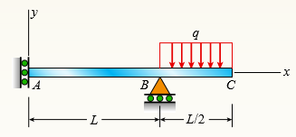
Derive the equations of the deflection curve for beam ABC with sliding support at A and roller support at B, supporting a uniform load of intensity q acting on the overhang portion of the beam (see figure). Also, determine deflection δC and angle of rotation θC. Use the fourth-order differential equation of the deflection curve (the load equation).
Transcribed Image Text:
mim A B L- - L/2-
> Solve the preceding problem using the numerical data: b = 90 mm, h = 280 mm, d = 210 mm, q = 14 kN/m, and L = 1.2 m. Data from Problem 21: Beam ABCD has a sliding support at A, roller supports at C and D, and a pin connection at B (see figure). Assume
> Beam ABCD has a sliding support at A, roller supports at C and D, and a pin connection at B (see figure). Assume that the beam has a rectangular cross section (b = 4 in., h = 12 in.). Uniform load q acts on ABC and a concentrated moment is applied at D.
> A cantilever beam with a T-section is loaded by an inclined force of magnitude 6.5 kN (see figure). The line of action of the force is inclined at an angle of 8 60 to the horizontal and intersects the top of the beam at the end cross section. The beam is
> A W 12 × 14 wide-flange beam is simply supported with a span length of 120 in. (see figure). The beam supports two anti-symmetrically placed concentrated loads of 7.5 kips each. At a cross section located 20 in. from the right ha
> A W 360 × 79 steel beam is fixed at A. The beam has a length of 2.5 m and is subjected to a linearly varying distributed load with maximum intensity qo = 500 N/m on segment AB and a uniformly distributed load of intensity q0 on segment BC. C
> A W 12 × 35 steel beam is fixed at A. The beam has length L = 6 ft and is subjected to a linearly varying distributed load with peak intensity qo = 830 lb/ft. Calculate the state of plane stress at point C located 3 in. below the top of the
> A W 200 × 41.7 wide-flange beam is simply supported with a span length of 2.5 m (see figure). The beam supports a concentrated load of 100 kN at 0.9 m from support B. At a cross section located 0.7 m from the left-hand support, determine the
> A beam with a wide-flange cross section (see figure) has the following dimensions: b = 5 in., t = 0.5 in., h = 12 in., and h1 = 10.5 in. The beam is simply supported with span length L = 10 ft and supports a uniform load q = 6 kips/ft. Calculate the prin
> A beam with a wide-flange cross section (see figure) has the following dimensions: b = 120 mm, t = 10 mm, h = 300 mm, and h1 = 260 mm. The beam is simply supported with span length L = 3.0m. AÂ concentrated load P = 120 kN acts at the midpoint
> A cantilever beam (width b = 3 in. and depth h = 6 in.) has a length L = 5 ft and is subjected to a point load P and a concentrated moment M = 20 kip-ft at end B. If normal stress σx = 0 at point C, located 0.5 in. below the top of the beam an
> A cantilever wood beam with a width b = 100 mm and depth h = 150 mm has a length L = 2 m and is subjected to point load P at mid-span and uniform load q = 15 N/m. (a) If the normal stress σx = 0 at point C, located 120 mm below the top of the
> Solve the preceding problem if the stress and dimensions are σ1 = 2450 psi, L = 80 in., b = 2.5 in., h = 10 in., and d = 2.5 in. Data from Problem 10: An overhanging beam ABC has a guided support at A, a rectangular cross section, and suppo
> An overhanging beam ABC has a guided support at A, a rectangular cross section, and supports an upward uniform load q = P/L over AB and a downward concentrated load P at the free end C (see figure). The span length from A to B is L, and the length of the
> A simple beam with a rectangular cross section (width, 3.5 in.; height, 12 in.) carries a trapezoid ally distributed load of 1400 lb/ft at A and 1000 lb/ft at B on a span of 14 ft (see figure). Find the principal stresses σ1 and σ2
> Solve the preceding problem for the following data: P = 160 kN, N = 200 kN, L = 2 m, b = 95 mm, h = 300 mm, and d = 200 mm. Data from Problem 7: A cantilever beam (L = 6 ft) with a rectangular cross section (b = 3.5 in., h = 12 in.) supports an upward
> A cantilever beam (L = 6 ft) with a rectangular cross section (b = 3.5 in., h = 12 in.) supports an upward load P = 35 kips at its free end. (a) Find the state of stress (σx, σy, and τxy in ksi) on a plane-stress element
> A cylindrical tank having a diameter d = 2.5 in. is subjected to internal gas pressure p = 600 psi and an external tensile load T = 1000 lb (see figure). Determine the minimum thickness t of the wall of the tank based upon an allowable shear stress of 30
> Beam ABC with an overhang BC is subjected to a linearly varying distributed load on span AB with peak intensity qo = 2500 N/m and a point load P = 1250 N applied at C. The beam has a width b = 100 mm and depth h = 200 mm. Find the state of plane stress a
> A beam with a width b = 6 in. and depth h = 8 in. is simply supported at A and B. The beam has a length L = 10 ft and is subjected to a linearly varying distributed load with peak intensity qo = 1500 lb/ft. Calculate the state of plane stress at point C
> A cantilever beam with a width b = 100 mm and depth h = 150 mm has a length L = 2 m and is subjected to a point load P = 500 N at B. Calculate the state of plane stress at point C located 50 mm below the top of the beam and 0.5 m to the right of point A.
> A simply supported beam is subjected to two point loads, each P = 500 lb, as shown in the figure. The beam has a cross section of 6 × 12 in. Find the state of plane stress at point C located 8 in. below the top of the beam and 0.5 ft to the
> Solve the preceding problem using the following data: beam cross section is 100 × 150 mm, length is 3 m, and point load is P = 5 kN at mid span. Point C is located 25 mm below the top of the beam and 0.5 m to the right of support
> A steel hanger bracket ABCD has a solid, circular cross section with a diameter of d = 2 in. The dimension variable is b = 6 in. (see figure). Load P = 1200 lb is applied at D along a line DH; the coordinates of point H are (8b, 25b, 3b). Find normal and
> A compound beam ABCD has a cable with force P anchored at C. The cable passes over a pulley at D, and force P acts in the 2x direction. There is a moment release just left of B. Neglect the self-weight of the beam and cable. Cable force P = 450 N and dim
> A plumber’s valve wrench is used to replace valves in plumbing fixtures. A simplified model of the wrench (see figure part a) consists of pipe AB (length L, outer diameter d2, inner diameter d1), which is fixed at A and has holes of a d
> Consider the mountain bike shown in the figure. To account for impact, crashes, and other loading uncertainties, a design load P = 5000 N is used to design the seat post. The length of the seat post is L = 254 mm. (a) Find the required diameter of the se
> Determine the maximum tensile, compressive, and shear stresses acting on the cross section of the tube at point A of the hitch bicycle rack shown in the figure. The rack is made up of 2 in. × 2 in. steel tubing which is 1/8 in. thick. Assume
> Solve the preceding problem using transverse load V = 300 N and torque T = 3.5 Nm? applied at point B. The bar has length L = 1.5 m and diameter d = 8 mm. Calculate the principal stresses and the maximum shear stress for element 2 located at the side of
> A mountain bike rider going uphill applies a force P = 65 N to each end of the handlebars ABCD, made of aluminum alloy 7075-T6, by pulling on the handlebar extenders (DF on right handlebar segment). Consider the right half of the handlebar assembly only
> A moveable steel stand supports an automobile engine weighing W = 750 lb, as shown in the figure part a. The stand is constructed of 2.5 in. × 2.5 in. × 1/8 in.-thick steel tubing. Once in position, the stand is restrained by pi
> A crank arm consists of a solid segment of length b1 and diameter d, a segment of length b2, and a segment of length b3, as shown in the figure. Two loads P act as shown: one parallel to 2x and another parallel to 2y. Each load P equals 1.2 kN. The crank
> An arm ABC lying in a horizontal plane and supported at A (see figure) is made of two identical solid steel bars AB and BC welded together at a right angle. Each bar is 22 in. long. (a) Knowing that the maximum tensile stress (principal stress) at the to
> A horizontal bracket ABC consists of two perpendicular arms AB of a length 0.75 m and BC of a length 0.5 m. The bracket has a solid, circular cross section with a diameter equal to 65 mm. The bracket is inserted in a frictionless sleeve at A (which is sl
> An L-shaped bracket lying in a horizontal plane supports a load P = 150 lb (see figure). The bracket has a hollow rectangular cross section with thickness t = 0.125 in. and outer dimensions b = 2.0 in. and h = 3.5 in. The centerline lengths of the arms a
> Repeat Problem 22 but replace the square tube column with a circular tube having a wall thickness t = 5 mm and the same cross- sectional area (3900 mm2) as that of the square tube in figure b in Problem 22. Also, add force Pz = 120 N at B. (a) Find the s
> A double-decker bicycle rack made up of square steel tubing is fixed at A (figure a). The weight of a bicycle is represented as a point load applied at B on a plane frame model of the rack (figure b). (a) Find the state of plane stress on an element C lo
> Determine the maximum tensile, compressive, and shear stresses at points A and B on the bicycle pedal crank shown in the figure. The pedal and crank are in a horizontal plane and points A and B are located on the top of the crank. The load P = 160 lb act
> A solid circular bar is fixed at point A. The bar is subjected to transverse load V = 70 lb and torque T = 300 lb-in. at point B. The bar has a length L = 60 in. and diameter d = 3 in. Calculate the principal normal stresses and the maximum shear stress
> A gondola on a ski lift is supported by two bent arms, as shown in the figure. Each arm is offset by the distance b = 180 mm from the line of action of the weight force W. The allowable stresses in the arms are 100 MPa in tension and 50 MPa in shear. If
> A bracket ABCD having a hollow circular cross section consists of a vertical arm AB (L = 6 ft), a horizontal arm BC parallel to the x0 axis, and a horizontal arm CD parallel to the z0 axis (see figure). The arms BC and CD have lengths b1 = 3.6 ft and b2
> Repeat the preceding problem but now find the stress state on Element A at the base. Let WS = 240 N, WL = 250 N, t = 5 mm, d = 360 mm. See the figure for the locations of element A and all loads. Data from Problem 17: A traffic light and signal pole
> A traffic light and signal pole is subjected to the weight of each traffic signal WS = 45 lb and the weight of the road lamp WL = 55 lb. The pole is fixed at the base. Find the principal normal stresses and the maximum shear stress on element B located 1
> A sign is supported by a pipe (see figure) having an outer diameter 110 mm and inner diameter 90 mm. The dimensions of the sign are 2.0 m × 1.0 m, and its lower edge is 3.0 m above the base. Note that the center of gravity of the
> A sign is supported by a pole of hollow circular cross section, as shown in the figure. The outer and inner diameters of the pole are 10.5 in. and 8.5 in., respectively. The pole is 42 ft high and weighs 4 kips. The sign has dimensions 8 ft ×
> A post having a hollow, circular cross section supports a P = 3.2 kN load acting at the end of an arm that is b = 1.5 m long (see figure). The height of the post is L = 9 m, and its section modulus is S = 2.65 × 105 mm3. Assume that the oute
> A segment of a generator shaft with a hollow circular cross section is subjected to a torque T = 240 kip-in (see figure). The outer and inner diameters of the shaft are 8.0 in. and 6.25 in., respectively. What is the maximum permissible compressive load
> A segment of a generator shaft is subjected to a torque T and an axial force P, as shown in the figure. The shaft is hollow (outer diameter d2 = 300 mm and inner diameter d1 = 250 mm) and delivers 1800Â kW at 4.0 Hz. If the compressive force P
> The hollow drill pipe for an oil well (see figure) is 6.2 in. in outer diameter and 0.75 in. in thickness. Just above the bit, the compressive force in the pipe (due to the weight of the pipe) is 62 kips and the torque (due to drilling) is 185 kip-in. De
> A W 310 × 52 steel beam is subjected to a point load P = 45 kN and a transverse load V = 20 kN at B. The beam has length L = 2 m. (a) Calculate the principal normal stresses and the maximum shear stress on element D located on the web right
> Derive the equation of the deflection curve for beam AB with sliding support at A and roller at B, carrying a triangularly distributed load of maximum intensity qo (see figure). Also, determine the maximum deflection δmax of the beam. Use th
> A beam on simple supports is subjected to a parabolic ally distributed load of intensity q(x) = 4qox (L - x)/L2, where qo is the maximum intensity of the load (see figure). Derive the equation of the deflection curve, and then determine the maximum defle
> A cantilever beam AB is subjected to a parabolic ally varying load of intensity q(x) = qo (L2 – x2)/L2, where qo is the maximum intensity of the load (see figure). Derive the equation of the deflection curve, and then determine the defl
> A beam with a uniform load has a sliding support at one end and spring support at the other. The spring has a stiffness k = 48EI/L3. Derive the equation of the deflection curve by starting with the third-order differential equation (the shear-force equat
> The simple beam AB shown in the figure has moments 2Mo and Mo acting at the ends. Derive the equation of the deflection curve, and then determine the maximum deflection δmax. Use the third-order differential equation of the deflection curve
> A cantilever beam has two triangular loads as shown in the figure. (a) Find an expression for beam deflection δC using superposition. (b) Find the required magnitude of load intensity q2 in terms of q1 so that the deflection at C is zero. (c
> Find required distance d (in terms of L) so that rotation θB = 0 is due to M and q loadings applied at the same time. Also, what is the resulting net rotation θA at support A? Moment M is applied at distance d from joint B.
> An overhanging beam ABC with a rectangular cross section has the dimensions shown in the figure. A weight W = 750 N drops onto end C of the beam. If the allowable normal stress in bending is 45 MPa, what is the maximum height h from which the weight may
> Find an expression for required moment MA (in terms of q and L) that will result in rotation θB = 0 due to MA and q loadings applied at the same time. Also, what is the resulting net rotation at support A? MA EI, L 2L/3
> Find an expression for required moment MA (in terms of q and L) that will result in rotation θB = 0 due to MA and q loadings applied at the same time. Also, what is the resulting net rotation at support A? MA mimum B EI, L 2L/3
> The wing of a small plane is represented by a simplified prismatic cantilever beam model acted on by the distributed loads shown in the figure. Assume constant EI = 1200 kN m2. Find the tip deflection and rotation at B. -1600 N/m 900 N/m 1.0 m 2.6 m
> The wing of a large commercial jet is represented by a simplified prismatic cantilever beam model with uniform load w and concentrated loads P at the two engine locations (see figure). Find expressions for the tip deflection and rotation at D in terms of
> A frame ABC is loaded at point C by a force P acting at an angle a to the horizontal (see figure). Both members of the frame have the same length and the same flexural rigidity. Determine the angle a so that the deflection of point C is in the same direc
> A beam ABCDE has simple supports at B and D and symmetrical overhangs at each end (see figure). The center span has length L and each overhang has length b. A uniform load of intensity q acts on the beam. (a) Determine the ratio b/L so that the deflectio
> A framework ABCD is acted on by force P at 2L/3 from B (see figure). Assume that EI is constant. (a) Find expressions for reactions at supports B and C. (b) Find expressions for angles of rotation at A, B, C, and D. (c) Find expressions for horizontal de
> A framework ABCD is acted on by counterclockwise moment M at A (see figure). Assume that EI is constant. (a) Find expressions for reactions at supports B and C. (b) Find expressions for angles of rotation at A, B, C, and D. (c) Find expressions for horiz
> The frame ABCD shown in the figure is squeezed by two collinear forces P acting at points A and D. What is the decrease d in the distance between points A and D when the loads P are applied? (The flexural rigidity EI is constant throughout the frame.)
> Find the horizontal deflection δh and vertical deflection δv at the free end C of the frame ABC shown in the figure. (The flexural rigidity EI is constant throughout the frame.) P B C с — C-
> A weight W = 4000 lb falls through a height h = 0.5 in onto the midpoint of a simple beam of length L = 10 ft (see figure). Assuming that the allowable bending stress in the beam is σallow = 18,000 psi and E = 30 × 106 psi, select
> The compound beam shown in the figure consists of a cantilever beam AB (length L) that is pin-connected to a simple beam BD (length 2L). After the beam is constructed, a clearance c exists between the beam and a support at C, midway between points B and
> Compound beam ABC is loaded by point load P = 1.5 kips at distance 2a/3 from point A and a triangularly distributed load on segment BC with peak intensity qo = 0.5 kips/ft. If length a = 5 ft and length b = 10 ft, find the deflection at B and rotation at
> Calculate the deflection at point C of a beam subjected to uniformly distributed load w = 275 N/m on span AB and point load P = 10 kN at C. Assume that L = 5 m and EI = 1.50 × 10⁷ Nm2. P B A L 4
> A steel beam ABC is simply supported at A and held by a high-strength steel wire at B (see figure). A load P = 240 lb acts at the free end C. The wire has axial rigidity EA = 1500 × 103 lb, and the beam has flexural rigidity EI = 36 Ã
> A compound beam ABCDE (see figure) consists of two parts (ABC and CDE) connected by a hinge (i.e., moment release) at C. The elastic support at B has stiffness k = EI/b3. Determine the deflection δE at the free end E due to the load P acting
> The compound beam ABC shown in the figure has a sliding support at A and a fixed support at C. The beam consists of two members joined by a pin connection (i.e., moment release) at B. Find the deflection δ under the load P. A C 36 -2b
> A beam ABCD rests on simple supports at B and C (see figure). The beam has a slight initial curvature so that end A is 18 mm above the elevation of the supports and end D is 12 mm above. What moments M1 and M2, acting at points A and D, respectively, wil
> An overhanging beam ABC with flexural rigidity EI = 15 kip-in2 is supported by a sliding support at A and by a spring of stiffness k at point B (see figure). Span AB has a length L = 30 in and carries a uniform load. The overhang BC has a length b = 15 i
> A thin metal strip of total weight W and length L is placed across the top of a flat table of width L/3 as shown in the figure. What is the clearance δ between the strip and the middle of the table? (The strip of metal has flexural rigidity
> The overhanging beam ABCD supports two concentrated loads P and Q (see figure). (a) For what ratio P/Q will the deflection at point B be zero? (b) For what ratio will the deflection at point D be zero? (c) If Q is replaced by a uniform load with intensit
> A weight W = 20 kN falls through a height h = 1.0 mm onto the midpoint of a simple beam of length L = 3 m (see figure). The beam is made of wood with square cross section (dimension d on each side) and E = 12 GPa. If the allowable bending stress in the w
> A simple beam AB supports a uniform load of intensity q acting over the middle region of the span (see figure). Determine the angle of rotation θA at the left hand support and the deflection δmax at the midpoint. B a a
> Determine the angle of rotation θB and deflection δB at the free end of a cantilever beam AB supporting a parabolic load defined by the equation q(x) = qox2/L2 (see figure). go B A
> A beam ABC having flexural rigidity EI = 75 kN m2 is loaded by a force P = 800 N at end C and tied down at end A by a wire having axial rigidity EA = 900 kN (see figure). What is the deflection at point C when the load P is applied? B P= 800 N 0.5 m
> A horizontal load P acts at end C of the bracket ABC shown in the figure. (a) Determine the deflection δC of point C. (b) Determine the maximum upward deflection δmax of member AB. H B L
> A beam ABCD consisting of a simple span BD and an overhang AB is loaded by a force P acting at the end of the bracket CEF (see figure). (a) Determine the deflection δA at the end of the overhang. (b) Under what conditions is this deflection
> A cantilever beam is subjected to a quadratic distributed load q(x) over the length of the beam (see figure). Find an expression for moment M in terms of the peak distributed load intensity qo so that the deflection is δB = 0. q(x) = qo
> Repeat Problem 15 for the anti- symmetric loading shown in the figure. Data from Problem 15: Use the method of superposition to find the angles of rotation θA and θB at the supports, and the maximum deflection δm
> Use the method of superposition to find the angles of rotation θA and θB at the supports, and the maximum deflection δmax for a simply supported beam subjected to symmetric loads P at distance a from each support. A
> A cantilever beam is subjected to load P at mid-span and counterclockwise moment M at B (see figure). (a) Find an expression for moment M in terms of the load P so that the reaction moment MA at A is equal to zero. (b) Find an expression for moment M in
> The cantilever beam ACB shown in the figure has flexural rigidity EI = 2.1 × 10⁶ kip-in2. Calculate the downward deflections δC and dB at points C and B, respectively, due to the simultaneous action of the moment of 35 kip-in. a
> A cantilever beam AB of length L = 6 ft is constructed of a W8 × 21 wide-flange section (see figure). A weight W = 1500 lb falls through a height h = 0.25 in onto the end of the beam. Calculate the maximum deflection δmax of the
> Determine the angle of rotation uB and deflection dB at the free end of a cantilever beam AB having a uniform load of intensity q acting over the middle third of its length (see figure). L
> What must be the equation y = f(x) of the axis of the slightly curved beam AB (see figure) before the load is applied in order that the load P, moving along the bar, always stays at the same level? |P B X- 7- L.
> Beam ACB hangs from two springs, as shown in the figure. The springs have stiffnesses k1 and k2 and the beam has flexural rigidity EI. (a) What is the downward displacement of point C, which is at the midpoint of the beam, when the moment Mo is applied?
> The cantilever beam AB shown in the figure has an extension BCD attached to its free end. A force P acts at the end of the extension. (a) Find the ratio a/L so that the vertical deflection of point B will be zero. (b) Find the ratio a/L so that the angle
> A simple beam AB supports five equally spaced loads P (see figure). (a) Determine the deflection δ1 at the midpoint of the beam. (b) If the same total load (5P) is distributed as a uniform load on the beam, what is the deflection Î&acu
> A cantilever beam AB carries three equally spaced concentrated loads, as shown in the figure. Obtain formulas for the angle of rotation θB and deflection δB at the free end of the beam. L L 3
> A cantilever beam carries a trapezoidal distributed load (see figure). Let wB = 2.5 kN/m, wA = 5.0 kN/m, and L = 2.5 m. The beam has a modulus E = 45 GPa and a rectangular cross section with width b = 200 mm and depth h = 300 mm. WA WB B LA L h
> A cantilever beam of a length L = 2.5 ft has a rectangular cross section (b = 4 in, h = 8 in) and modulus E = 10,000 ksi. The beam is subjected to a linearly varying distributed load with a peak intensity qo = 900 lb/ft. go A. B L
> Beam ABC is loaded by a uniform load q and point load P at joint C. Using the method of superposition, calculate the deflection at joint C. Assume that L = 4 m, a = 2 m, q = 15 kN/m , P = 7.5 kN , E = 200 GPa, and I = 70.8 × 106 mm4. C
> Copper beam AB has circular cross section with a radius of 0.25 in. and length L = 3 ft. The beam is subjected to a uniformly distributed load w = 3.5 lb/ft. Calculate the required load P at joint B so that the total deflection at joint B is zero. Assume

