Question: A stepped shaft ACB having solid circular
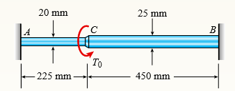
A stepped shaft ACB having solid circular cross sections with two different diameters is held against rotation at the ends (see figure).
(a) If the allowable shear stress in the shaft is 43 MPa, what is the maximum torque (To)max that may be applied at section C?
(b) Find (To)max if the maximum angle of twist is limited to 1.85°. Let G = 28 GPa.
Transcribed Image Text:
20 mm 25 mm A B To – 225 mm- 450 mm
> A propeller shaft for a small yacht is made of a solid steel bar 104 mm in diameter. The allowable stress in shear is 48 MPa, and the allowable rate of twist is 2.0° in 3.5 meters. (a) Assuming that the shear modulus of elasticity is G = 80 GP
> A circular tube of aluminum is subjected to torsion by torques T applied at the ends (see figure). The bar is 24 in. long, and the inside and outside diameters are 1.25 in. and 1.75 in., respectively. It is determined by measurement that the angle of twi
> A high-strength steel drill rod used for boring a hole in the earth has a diameter of 0.5 in. (see figure). The allowable shear stress in the steel is 40Â ksi and the shear modulus of elasticity is 11,600 ksi. (a) What is the minimum required
> An aluminum bar of solid circular cross section is twisted by torques T acting at the ends (see figure). The dimensions and shear modulus of elasticity are L = 1.4 m, d = 32 mm, and G = 28 GPa. (a) Determine the torsional stiffness of the bar. (b) If the
> While removing a wheel to change a tire, a driver applies forces P = 25 lb at the ends of two of the arms of a lug wrench (see figure). The wrench is made of steel with shear modulus of elasticity G = 11.4 × 10⁶ psi. Each arm of the wrench i
> When drilling a hole in a table leg, a furniture maker uses a hand-operated drill (see figure) with a bit of diameter d = 4.0 mm. (a) If the resisting torque supplied by the table leg is equal to 0.3 Nm? what is the maximum shear stress in the drill bit?
> A prospector uses a hand-powered winch (see figure) to raise a bucket of ore in his mine shaft. The axle of the winch is a steel rod of diameter d = 0.625 in. Also, the distance from the center of the axle to the center of the lifting rope is b = 4.0 in.
> A laminated plastic beam of square cross section is built up by gluing together three strips, each 10 mm × 30 mm in cross section (see figure). The beam has a total weight of 3.6 N and is simply supported with span length L = 360 mm. Conside
> A copper tube with circular cross section has length L = 1.25 m, thickness t = 2 mm, and shear modulus of elasticity G = 45 GPa. The bar is designed to carry a 300 Nm? torque acting at the ends. If the allowable shear stress is 25 MPa and the allowable a
> Repeat Problem 1, but now use a circular tube with outer diameter do = 2.5 in. and inner diameter di = 1.5 in. Data from Problem 1: A solid steel bar of circular cross section has diameter d = 2.5 in, L = 60 in, and shear modulus of elasticity G = 11.
> Two circular aluminum pipes of equal length L = 24 in. are loaded by torsional moments T (see figure). Pipe 1 has outside and inside diameters d2 = 3 in and d1 = 2.5 in, respectively. Pipe 2 has a constant outer diameter of d2 along its entire length&Aci
> A solid aluminum bar (G = 2 7 GPa) of diameter d = 40 mm is subjected to torques T = 300 Nm? acting in the directions shown in the figure. (a) Determine the maximum shear, tensile, and compressive stresses in the bar and show these stresses on sketches o
> A solid steel bar (G = 11.8 × 10⁶ psi) of diameter d = 2.0 in. is subjected to torques T = 8.0 kip-in. acting in the directions shown in the figure. (a) Determine the maximum shear, tensile, and compressive stresses in the bar and show these
> An aluminum tube has inside diameter d1 = 50 mm, shear modulus of elasticity G = 27 GPa, v = 0.33, and torque T = 4.0 kNm? The allowable shear stress in the aluminum is 50 MPa, and the allowable normal strain is 900 × 10-6. (a) Determine the required out
> The normal strain in the 45° direction on the surface of a circular tube (see figure) is 880 × 10-6 when the torque T = 750 lb-in. The tube is made of copper alloy with G = 6.2 × 10⁶ psi and n = 0.35. (a) If the outsi
> A solid circular bar of steel (G = 78 GPa) transmits a torque T = 360 Nm? The allowable stresses in tension, compression, and shear are 90 MPa, 70 MPa, and 40 MPa, respectively. Also, the allowable tensile strain is 220 × 10-6. (a) Determine the minimum
> A steel tube (G = 11.5 × 10⁶ psi) has an outer diameter d2 = 2.0 in. and an inner diameter d1 = 1.5 in. When twisted by a torque T, the tube develops a maximum normal strain of 170 × 10-6. What is the magnitude of the applied torque T?
> A solid circular bar of diameter d = 50 mm (see figure) is twisted in a testing machine until the applied torque reaches the value T = 500 Nm?. At this value of torque, a strain gage oriented at 45° to the axis of the bar gives a reading &Icir
> A laminated wood beam on simple supports (figure part a) is built up by gluing together four 2 in. × 4 in boards (actual dimensions) to form a solid beam 4 in. × 8 in in cross section, as shown in the figure part b. The allowabl
> A tubular bar with outside diameter d2 = 4.0 in. is twisted by torques T = 70.0 kip-in. (see figure). Under the action of these torques, the maximum tensile stress in the bar is found to be 6400 psi. (a) Determine the inside diameter d1 of the bar. (b) I
> A hollow steel bar (G = 8 0GPa) is twisted by torques T (see figure). The twisting of the bar produces a maximum shear strain γmax = 640 × 10-6 rad. The bar has outside and inside diameters of 150 mm and 120 mm, respectively. (a)
> A hollow aluminum shaft (see figure) has an outside diameter d2 = 4.0 in. and inside diameter d1 = 2.0 in. When twisted by torques T, the shaft has an angle of twist per unit distance equal to 0.548 /ft. The shear modulus of elasticity of the aluminum is
> A circular steel tube with an outer diameter of 75 mm and inner diameter of 65 mm is subjected to torques T at its ends. Calculate the maximum permissible torque Tmax if the allowable normal strain is εa = 5 Ã&
> The shaft ABC shown in the figure is driven by a motor that delivers 300 kW at a rotational speed of 32 Hz. The gears at B and C take out 120Â kW and 180Â kW, respectively. The lengths of the two parts of the shaft are L1 = 1.5 m an
> A motor delivers 275 hp at 1000 rpm to the end of a shaft (see figure). The gears at B and C take out 125 and 150 hp, respectively. Determine the required diameter d of the shaft if the allowable shear stress is 7500 psi and the angle of twist between th
> What is the maximum power that can be delivered by a hollow propeller shaft (outside diameter 50 mm, inside diameter 40 mm, and shear modulus of elasticity 80 GPa) turning at 600 rpm if the allowable shear stress is 100 MPa and the allowable rate of twis
> A propeller shaft of solid circular cross section and diameter d is spliced by a collar of the same material (see figure). The collar is securely bonded to both parts of the shaft. What should be the minimum outer diameter d1 of the collar in order that
> A tubular shaft being designed for use on a construction site must transmit 120 kW at 1.75 Hz. The inside diameter of the shaft is to be one-half of the outside diameter. If the allowable shear stress in the shaft is 45 MPa, what is the minimum required
> A hollow circular shaft for use in a pumping station is being designed with an inside diameter equal to 0.75 times the outside diameter. The shaft must transmit 400 hp at 400 rpm without exceeding the allowable shear stress of 6000 psi. Determine the min
> A beam of rectangular cross section (width b and height h) supports a uniformly distributed load along its entire length L. The allowable stresses in bending and shear are σallow and τallow, respectively. (a) If the beam is simply supported, what is the
> The drive shaft for a truck (outer diameter 60 mm and inner diameter 40 mm) is running at 2500Â rpm (see figure). (a) If the shaft transmits 150 kW, what is the maximum shear stress in the shaft? (b) If the allowable shear stress is 30 MPa, wh
> The propeller shaft of a large ship has an outside diameter 18 in. and inside diameter 12 in., as shown in the figure. The shaft is rated for a maximum shear stress of 4500 psi. (a) If the shaft is turning at 100 rpm, what is the maximum horsepower that
> A solid steel shaft ABC with diameter d = 40 mm is driven at A by a motor that transmits 75Â kW to the shaft at 15 Hz. The gears at B and C drive machinery requiring power equal to 50 kW and 25Â kW, respectively. Compute the maximum
> A motor driving a solid circular steel shaft with diameter d = 1.5 in. transmits 50 hp to a gear at B. The allowable shear stress in the steel is 6000 psi. Calculate the required speed of rotation (number of revolutions per minute) so that the shear stre
> A motor drives a shaft at 12 Hz and delivers 20 kW of power (see figure). (a) If the shaft has a diameter of 30 mm, what is the maximum shear stress Ï„max in the shaft? (b) If the maximum allowable shear stress is 40Â MPa, what is th
> Two pipes (L1 = 2.5 m and L2 = 1.5 m) are joined at B by flange plates (thickness tf = 14 mm) with five bolts (dbf = 1 3 mm) arranged in a circular pattern (see figure). Also, each pipe segment is attached to a wall (at A and C, see figure) using a base
> A uniformly tapered aluminum-alloy tube AB of circular cross section and length L is fixed against rotation at A and B, as shown in the figure. The outside diameters at the ends are dA and dB = 2dA. A hollow section of length L/2 and constant thickness t
> A steel shaft (Gs = 8 0GPa) of total length L = 3.0 m is encased for one-third of its length by a brass sleeve (Gb = 4 0GPa) that is securely bonded to the steel (see figure). The outer diameters of the shaft and sleeve are d1 = 70 mm and d2 = 90 mm, res
> The composite shaft shown in the figure is manufactured by shrink-fitting a steel sleeve over a brass core so that the two parts act as a single solid bar in torsion. The outer diameters of the two parts are d1 = 1.6 in. for the brass core and d2 = 2.0 i
> The composite shaft shown in the figure is manufactured by shrink-fitting a steel sleeve over a brass core so that the two parts act as a single solid bar in torsion. The outer diameters of the two parts are d1 = 40 mm for the brass core and d2 = 50 mm f
> A steel beam of length L = 16 in and cross- sectional dimensions b = 0.6 in and h = 2 in (see figure) supports a uniform load of intensity q = 240 lb/in, which includes the weight of the beam. Calculate the shear stresses in the beam (at the cross sectio
> A rectangular beam with semicircular notches, as shown in part b of the figure, has dimensions h = 120 mm and h1 = 100 mm. The maximum allowable bending stress in the plastic beam is σmax = 6 MPa, and the bending moment is M = 150 Nm? Determin
> A solid steel bar of diameter d1 = 1.50 in. is enclosed by a steel tube of outer diameter d3 = 2.25 in. and inner diameter d2 = 1.75 in. (see figure). Both bar and tube are held rigidly by a support at end A and joined securely to a rigid plate at end B.
> A solid steel bar of diameter d1 = 25.0mm is enclosed by a steel tube of outer diameter d3 = 37.5 mm and inner diameter d2 = 30.0mm (see figure). Both bar and tube are held rigidly by a support at end A and joined securely to a rigid plate at end B. The
> A circular bar AB with ends fixed against rotation has a hole extending for half of its length (see figure). The outer diameter of the bar is d2 = 3.0 in., and the diameter of the hole is d1 = 2.4 in. The total length of the bar is L = 50 in. (a) At what
> A circular bar AB of length L is fixed against rotation at the ends and loaded by a distributed torque t(x) that varies linearly in intensity from zero at end A to to at end B (see figure). (a) Obtain formulas for the fixed-end torques TA and TB. (b) Fin
> Two sections of steel drill pipe, joined by bolted flange plates at B, are subjected to a concentrated torque 4000 kip-in. at x = 3 ft, and a uniformly distributed torque to = 50 kip-ft/ft is applied on pipe BC. Let G = 11,800 ksi and assume that pipes A
> A solid circular aluminum bar AB is fixed at both ends and loaded by a uniformly distributed torque 150 Nm/m? The bar has diameter d = 30 mm. Calculate the reactive torques at the supports and the angle of twist at mid span. Assume that G = 28 GPa.
> A stepped shaft ACB is held against rotation at ends A and B and subjected to a torque To acting at section C (see figure). The two segments of the shaft (AC and CB) have diameters dA and dB, respectively, and polar moments of inertia IpA and IpB, respec
> A stepped shaft ACB having solid circular cross sections with two different diameters is held against rotation at the ends (see figure). (a) If the allowable shear stress in the shaft is 6000 psi, what is the maximum torque (To)max that may be applied at
> A hollow steel shaft ACB of outside diameter 50 mm and inside diameter 40 mm is held against rotation at ends A and B (see figure). Horizontal forces P are applied at the ends of a vertical arm that is welded to the shaft at point C. Determine the allowa
> A cantilever beam of length L = 2 m supports a load P = 8.0 kN (see figure). The beam is made of wood with cross-sectional dimensions 120 mm × 200 mm. Calculate the shear stresses due to the load P at points located 25 mm, 50 mm, 75 mm, and
> A solid circular shaft AB of diameter d is fixed against rotation at both ends (see figure). A circular disk is attached to the shaft at the location shown. What is the largest permissible angle of rotation φmax of the disk if the allowable sh
> A solid circular bar ABCD with fixed supports at ends A and D is acted upon by two equal and oppositely directed torques To, as shown in the figure. The torques are applied at points B and C, each of which is located at distance x from one end of the bar
> A heavy flywheel rotating at n revolutions per minute is rigidly attached to the end of a shaft of diameter d (see figure). If the bearing at A suddenly freezes, what will be the maximum angle of twist Ï• of the shaft? What is the corresponding
> A hollow circular tube A fits over the end of a solid circular bar B, as shown in the figure. The far ends of both bars are fixed. Initially, a hole through bar B makes an angle β with a line through two holes in tube A. Then bar B is twisted
> A thin-walled hollow tube AB of conical shape has constant thickness t and average diameters dA and dB at the ends (see figure). (a) Determine the strain energy U of the tube when it is subjected to pure torsion by torques T. (b) Determine the angle of t
> Derive a formula for the strain energy U of the cantilever bar shown in the figure. The bar has circular cross sections and length L. It is subjected to a distributed torque of intensity t per unit distance. The intensity varies linearly from t = 0 at th
> A statically indeterminate stepped shaft ACB is fixed at ends A and B and loaded by a torque To at point C (see figure). The two segments of the bar are made of the same material, have lengths LA and LB, and have polar moments of inertia IpA and IpB. Det
> Obtain a formula for the strain energy U of the statically indeterminate circular bar shown in the figure. The bar has fixed supports at ends A and B and is loaded by torques 2To and To at points C and D, respectively. 2To To A B D
> A cantilever bar of circular cross section and length L is fixed at one end and free at the other (see figure). The bar is loaded by a torque T at the free end and by a distributed torque of constant intensity t per unit distance along the length of the
> A circular tube AB is fixed at one end and free at the other. The tube is subjected to concentrated torques as shown in the figure. If the outer radius of the tube is 1.5 in. and the thickness is 3/4 in., calculate the strain energy stored in the tube. L
> Two wood beams, each of rectangular cross section (3.0in. × 4.0in, actual dimensions), are glued together to form a solid beam with dimensions 6.0in. × 4.0in. (see figure). The beam is simply supported with a span of 8 ft. (a) W
> A stepped shaft of solid circular cross sections (see figure) has length L = 0.80 m, diameter d2 = 40 mm, and diameter d1 = 30 mm. The material is steel with G = 80 GPa. Determine the strain energy U of the shaft if the angle of twist is 1.0°.
> A stepped shaft of solid circular cross sections (see figure) has length L = 45 in., diameter d2 = 1.2 in, and diameter d1 = 1.0 in. The material is brass with G = 5.6 × 10⁶ psi. Determine the strain energy U of the shaft if the angle of twi
> A thin-walled rectangular tube has uniform thickness t and dimensions a × b to the median line of the cross section (see figure). How does the shear stress in the tube vary with the ratio β = a/b if the total length Lm of the med
> A thin tubular shaft with a circular cross section (see figure) and with inside diameter 100 mm is subjected to a torque of 5000 Nm. If the allowable shear stress is 42 MPa, determine the required wall thickness t by using (a) the approximate theory for
> A tubular aluminum bar (G = 4 × 10⁶ psi) of square cross section (see figure) with outer dimensions 2 in. × 2 in. must resist a torque T = 3000 lb-in. Calculate the minimum required wall thickness mint if the allowable shear str
> Compare the angle of twist φ1 for a thin walled circular tube (see figure) calculated from the approximate theory for thin-walled bars with the angle of twist f2 calculated from the exact theory of torsion for circular bars. (a) Express the ra
> A torque T is applied to a thin-walled tube having a cross section in the shape of a regular hexagon with constant wall thickness t and side length b (see figure). Obtain formulas for the shear stress τ and the rate of twist θ.
> Calculate the shear stress Ï„ and the angle of twist Ï• (in degrees) for a steel tube (G = 7 6GPa) having the cross section shown in the figure. The tube has length L = 1.5 m and is subjected to a torque T = 10 kNm? Įt= 8 mm r= 5
> A thin-walled steel tube having an elliptical cross section with constant thickness t (see figure) is subjected to a torque T = 18 kip-in. Determine the shear stress τ and the rate of twist θ (in degrees per inch) if G = 12 &Atild
> A thin-walled circular tube and a solid circular bar of the same material (see figure) are subjected to torsion. The tube and bar have the same cross-sectional area and the same length. What is the ratio of the strain energy U1 in the tube to the strain
> A simply supported wood beam with overhang is subjected to uniformly distributed load q. The beam has a rectangular cross section with width b = 200 mm and height h = 250 mm. Determine the maximum permissible value q if the allowable bending stress is &I
> A square tube section has side dimension of 20 in. and thickness of 0.5 in. If the section is used for a 10-ft-long beam subjected to 1250 kip-in. torque at both ends, calculate the maximum shear stress and the angle of twist between the ends. Use G = 11
> A thin-walled steel tube of rectangular cross section (see figure) has centerline dimensions b = 150 mm and h = 100 mm. The wall thickness t is constant and equal to 6.0 mm. (a) Determine the shear stress in the tube due to a torque T = 1650 Nm? (b) Dete
> A thin-walled aluminum tube of rectangular cross section (see figure) has a centerline dimensions b = 6.0 in. and h = 4.0in. The wall thickness t is constant and equal to 0.25 in. (a) Determine the shear stress in the tube due to a torque T = 15 kip-in.
> A solid circular bar having diameter d is to be replaced by a rectangular tube having cross- sectional dimensions d × 2d to the median line of the cross section (see figure). Determine the required thickness tmin of the tube so that the maxi
> A solid circular bar of copper (G = 4 5 GPa) with length L = 0.75 m and diameter d = 40 mm is subjected to pure torsion by torques T acting at the ends (see figure). (a) Calculate the amount of strain energy U stored in the bar when the maximum shear str
> A stepped shaft (see figure) has diameter D2 = 1.5 in. and a full quarter-circular fillet. The allowable shear stress is 15,000 psi and the load T = 4800 lb-in. What is the smallest permissible diameter D1? |D2 R |D1 T T
> The stepped shaft shown in the figure is required to transmit 600 kW of power at 400 rpm. The shaft has a full quarter-circular fillet, and the smaller diameter D1 = 100 mm. If the allowable shear stress at the stress concentration is 100 MPa, at what di
> A full quarter-circular fillet is used at the shoulder of a stepped shaft having diameter D2 = 1.0 in. (see figure). A torque T = 500 lb-in. acts on the shaft. Determine the shear stress Ï„max at the stress concentration for values as follows:
> A stepped shaft with diameters D1 = 40 mm and D2 = 60 mm is loaded by torques T = 1100 Nm? (see figure). If the allowable shear stress at the stress concentration is 120 MPa, what is the smallest radius Rmin that may be used for the fillet? |D2 R |D
> The stresses acting on element B on the web of a train rail (see figure part a of Problem 5) are found to be 5700 psi in compression in the horizontal direction and 2300 psi in compression in the vertical direction (see figure). Also, shear stresses of m
> A simply supported wood beam is subjected to uniformly distributed load q. The width of the beam is 6 in. and the height is 8 in. Determine the normal stress and the shear stress at point C. Show these stresses on a sketch of a stress element at point C.
> Solve the preceding problem if the stresses acting on element A on the web of a train rail (see figure part a of Problem 5) are found to be 40 MPa in tension in the horizontal direction and 160 MPa in compression in the vertical direction. Also, shear st
> The stresses acting on element A on the web of a train rail (see figure part a) are found to be 6500 psi tension in the horizontal direction and 18,500 psi compression in the vertical direction (see figure part b). Also, shear stresses with a magnitude o
> The stresses on an element are σx = 1000 psi, σy = 500 psi, and τxy = 350 psi. Find the stresses acting on an element oriented at an angle θ = 25°. Show these stresses on the rotated element.
> Solve the preceding problem for an element in plane stress on the bottom surface of a fuel tanker (figure part a); stresses are σx = 105 MPa, σy = 75 MPa, and τxy = 25 MPa. Determine the stresses acting on an element orie
> The stresses on the bottom surface of a fuel tanker (figure part a) are known to be σx = 7750 psi, σy = 1175 psi, and Ï„xy = 940 psi (figure part b). Determine the stresses acting on an element oriented at an angle Î
> A simply supported wood beam is subjected to point load P at mid-span. The normal stress on element C is known to be σx = 12 MPa. Find the maximum shear stress on the element and show the state of stress on a sketch of a properly oriented elem
> A simply supported wood beam is subjected to point load P at mid-span. The stresses on element C are known to be σx = –92 psi and τxy = –7 psi. Find the principal stresses on the element and show
> An element in plane stress on the surface of an automobile drive shaft (see figure) is subjected to stresses of σx = -45 MPa and τxy = 39 MPa (see figure). It is known that one of the principal stresses equals 41 MPa in tension. (a)
> The stresses at a point on the down tube of a bicycle frame are σx = 4800 psi and τxy = –1950 psi (see figure). It is known that one of the principal stresses equals 6375 psi in tension. (a) Determine the stress &I
> Calculate the maximum shear stress τmax and the maximum bending stress αmax in a wood beam (see figure) carrying a uniform load of 22.5 kN/m (which includes the weight of the beam) if the length is 1.95 m and the cross section is
> The stresses acting on a stress element on the arm of a power excavator (see figure) are σx = 52 MPa and τxy = 33 MPa (see figure). What is the allowable range of values for the stress y s if the maximum shear stress is limited to &
> At a point on the web of a girder on a gantry crane, the stresses acting on the x face of a stress element are σx = 6250 psi and τxy = 1425 psi (see figure). What is the allowable range of values for the stress σy if the
> σx = -108 MPa, σy = 58MPa, τxy = -58MPa Data for Problem 22: An element in plane stress (see figure) is subjected to stresses σx, σy, and τxy. (a) Determine the principal stresses and s
> σx = -3300 psi, σy = -11,000psi, τxy = 4500 psi. Data for Problem 21: An element in plane stress (see figure) is subjected to stresses σx, σy, and τxy. (a) Determine the principal stres
> σx = 16.5 MPa, σy = -91 MPa, τxy = -39 MPa. Data for Problem 20: An element in plane stress (see figure) is subjected to stresses σx, σy, and τxy. (a) Determine the principal stresses a

