Question:
σx = -108 MPa, σy = 58MPa, τxy = -58MPa
Data for Problem 22:
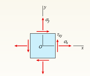
An element in plane stress (see figure) is subjected to stresses σx, σy, and τxy.
(a) Determine the principal stresses and show them on a sketch of a properly oriented element.
(b) Determine the maximum shear stresses and associated normal stresses and show them on a sketch of a properly oriented element.

Transcribed Image Text:
Txy Txy
> A stepped shaft ACB having solid circular cross sections with two different diameters is held against rotation at the ends (see figure). (a) If the allowable shear stress in the shaft is 43 MPa, what is the maximum torque (To)max that may be applied at s
> A stepped shaft ACB having solid circular cross sections with two different diameters is held against rotation at the ends (see figure). (a) If the allowable shear stress in the shaft is 6000 psi, what is the maximum torque (To)max that may be applied at
> A hollow steel shaft ACB of outside diameter 50 mm and inside diameter 40 mm is held against rotation at ends A and B (see figure). Horizontal forces P are applied at the ends of a vertical arm that is welded to the shaft at point C. Determine the allowa
> A cantilever beam of length L = 2 m supports a load P = 8.0 kN (see figure). The beam is made of wood with cross-sectional dimensions 120 mm × 200 mm. Calculate the shear stresses due to the load P at points located 25 mm, 50 mm, 75 mm, and
> A solid circular shaft AB of diameter d is fixed against rotation at both ends (see figure). A circular disk is attached to the shaft at the location shown. What is the largest permissible angle of rotation φmax of the disk if the allowable sh
> A solid circular bar ABCD with fixed supports at ends A and D is acted upon by two equal and oppositely directed torques To, as shown in the figure. The torques are applied at points B and C, each of which is located at distance x from one end of the bar
> A heavy flywheel rotating at n revolutions per minute is rigidly attached to the end of a shaft of diameter d (see figure). If the bearing at A suddenly freezes, what will be the maximum angle of twist Ï• of the shaft? What is the corresponding
> A hollow circular tube A fits over the end of a solid circular bar B, as shown in the figure. The far ends of both bars are fixed. Initially, a hole through bar B makes an angle β with a line through two holes in tube A. Then bar B is twisted
> A thin-walled hollow tube AB of conical shape has constant thickness t and average diameters dA and dB at the ends (see figure). (a) Determine the strain energy U of the tube when it is subjected to pure torsion by torques T. (b) Determine the angle of t
> Derive a formula for the strain energy U of the cantilever bar shown in the figure. The bar has circular cross sections and length L. It is subjected to a distributed torque of intensity t per unit distance. The intensity varies linearly from t = 0 at th
> A statically indeterminate stepped shaft ACB is fixed at ends A and B and loaded by a torque To at point C (see figure). The two segments of the bar are made of the same material, have lengths LA and LB, and have polar moments of inertia IpA and IpB. Det
> Obtain a formula for the strain energy U of the statically indeterminate circular bar shown in the figure. The bar has fixed supports at ends A and B and is loaded by torques 2To and To at points C and D, respectively. 2To To A B D
> A cantilever bar of circular cross section and length L is fixed at one end and free at the other (see figure). The bar is loaded by a torque T at the free end and by a distributed torque of constant intensity t per unit distance along the length of the
> A circular tube AB is fixed at one end and free at the other. The tube is subjected to concentrated torques as shown in the figure. If the outer radius of the tube is 1.5 in. and the thickness is 3/4 in., calculate the strain energy stored in the tube. L
> Two wood beams, each of rectangular cross section (3.0in. × 4.0in, actual dimensions), are glued together to form a solid beam with dimensions 6.0in. × 4.0in. (see figure). The beam is simply supported with a span of 8 ft. (a) W
> A stepped shaft of solid circular cross sections (see figure) has length L = 0.80 m, diameter d2 = 40 mm, and diameter d1 = 30 mm. The material is steel with G = 80 GPa. Determine the strain energy U of the shaft if the angle of twist is 1.0°.
> A stepped shaft of solid circular cross sections (see figure) has length L = 45 in., diameter d2 = 1.2 in, and diameter d1 = 1.0 in. The material is brass with G = 5.6 × 10⁶ psi. Determine the strain energy U of the shaft if the angle of twi
> A thin-walled rectangular tube has uniform thickness t and dimensions a × b to the median line of the cross section (see figure). How does the shear stress in the tube vary with the ratio β = a/b if the total length Lm of the med
> A thin tubular shaft with a circular cross section (see figure) and with inside diameter 100 mm is subjected to a torque of 5000 Nm. If the allowable shear stress is 42 MPa, determine the required wall thickness t by using (a) the approximate theory for
> A tubular aluminum bar (G = 4 × 10⁶ psi) of square cross section (see figure) with outer dimensions 2 in. × 2 in. must resist a torque T = 3000 lb-in. Calculate the minimum required wall thickness mint if the allowable shear str
> Compare the angle of twist φ1 for a thin walled circular tube (see figure) calculated from the approximate theory for thin-walled bars with the angle of twist f2 calculated from the exact theory of torsion for circular bars. (a) Express the ra
> A torque T is applied to a thin-walled tube having a cross section in the shape of a regular hexagon with constant wall thickness t and side length b (see figure). Obtain formulas for the shear stress τ and the rate of twist θ.
> Calculate the shear stress Ï„ and the angle of twist Ï• (in degrees) for a steel tube (G = 7 6GPa) having the cross section shown in the figure. The tube has length L = 1.5 m and is subjected to a torque T = 10 kNm? Įt= 8 mm r= 5
> A thin-walled steel tube having an elliptical cross section with constant thickness t (see figure) is subjected to a torque T = 18 kip-in. Determine the shear stress τ and the rate of twist θ (in degrees per inch) if G = 12 &Atild
> A thin-walled circular tube and a solid circular bar of the same material (see figure) are subjected to torsion. The tube and bar have the same cross-sectional area and the same length. What is the ratio of the strain energy U1 in the tube to the strain
> A simply supported wood beam with overhang is subjected to uniformly distributed load q. The beam has a rectangular cross section with width b = 200 mm and height h = 250 mm. Determine the maximum permissible value q if the allowable bending stress is &I
> A square tube section has side dimension of 20 in. and thickness of 0.5 in. If the section is used for a 10-ft-long beam subjected to 1250 kip-in. torque at both ends, calculate the maximum shear stress and the angle of twist between the ends. Use G = 11
> A thin-walled steel tube of rectangular cross section (see figure) has centerline dimensions b = 150 mm and h = 100 mm. The wall thickness t is constant and equal to 6.0 mm. (a) Determine the shear stress in the tube due to a torque T = 1650 Nm? (b) Dete
> A thin-walled aluminum tube of rectangular cross section (see figure) has a centerline dimensions b = 6.0 in. and h = 4.0in. The wall thickness t is constant and equal to 0.25 in. (a) Determine the shear stress in the tube due to a torque T = 15 kip-in.
> A solid circular bar having diameter d is to be replaced by a rectangular tube having cross- sectional dimensions d × 2d to the median line of the cross section (see figure). Determine the required thickness tmin of the tube so that the maxi
> A solid circular bar of copper (G = 4 5 GPa) with length L = 0.75 m and diameter d = 40 mm is subjected to pure torsion by torques T acting at the ends (see figure). (a) Calculate the amount of strain energy U stored in the bar when the maximum shear str
> A stepped shaft (see figure) has diameter D2 = 1.5 in. and a full quarter-circular fillet. The allowable shear stress is 15,000 psi and the load T = 4800 lb-in. What is the smallest permissible diameter D1? |D2 R |D1 T T
> The stepped shaft shown in the figure is required to transmit 600 kW of power at 400 rpm. The shaft has a full quarter-circular fillet, and the smaller diameter D1 = 100 mm. If the allowable shear stress at the stress concentration is 100 MPa, at what di
> A full quarter-circular fillet is used at the shoulder of a stepped shaft having diameter D2 = 1.0 in. (see figure). A torque T = 500 lb-in. acts on the shaft. Determine the shear stress Ï„max at the stress concentration for values as follows:
> A stepped shaft with diameters D1 = 40 mm and D2 = 60 mm is loaded by torques T = 1100 Nm? (see figure). If the allowable shear stress at the stress concentration is 120 MPa, what is the smallest radius Rmin that may be used for the fillet? |D2 R |D
> The stresses acting on element B on the web of a train rail (see figure part a of Problem 5) are found to be 5700 psi in compression in the horizontal direction and 2300 psi in compression in the vertical direction (see figure). Also, shear stresses of m
> A simply supported wood beam is subjected to uniformly distributed load q. The width of the beam is 6 in. and the height is 8 in. Determine the normal stress and the shear stress at point C. Show these stresses on a sketch of a stress element at point C.
> Solve the preceding problem if the stresses acting on element A on the web of a train rail (see figure part a of Problem 5) are found to be 40 MPa in tension in the horizontal direction and 160 MPa in compression in the vertical direction. Also, shear st
> The stresses acting on element A on the web of a train rail (see figure part a) are found to be 6500 psi tension in the horizontal direction and 18,500 psi compression in the vertical direction (see figure part b). Also, shear stresses with a magnitude o
> The stresses on an element are σx = 1000 psi, σy = 500 psi, and τxy = 350 psi. Find the stresses acting on an element oriented at an angle θ = 25°. Show these stresses on the rotated element.
> Solve the preceding problem for an element in plane stress on the bottom surface of a fuel tanker (figure part a); stresses are σx = 105 MPa, σy = 75 MPa, and τxy = 25 MPa. Determine the stresses acting on an element orie
> The stresses on the bottom surface of a fuel tanker (figure part a) are known to be σx = 7750 psi, σy = 1175 psi, and Ï„xy = 940 psi (figure part b). Determine the stresses acting on an element oriented at an angle Î
> A simply supported wood beam is subjected to point load P at mid-span. The normal stress on element C is known to be σx = 12 MPa. Find the maximum shear stress on the element and show the state of stress on a sketch of a properly oriented elem
> A simply supported wood beam is subjected to point load P at mid-span. The stresses on element C are known to be σx = –92 psi and τxy = –7 psi. Find the principal stresses on the element and show
> An element in plane stress on the surface of an automobile drive shaft (see figure) is subjected to stresses of σx = -45 MPa and τxy = 39 MPa (see figure). It is known that one of the principal stresses equals 41 MPa in tension. (a)
> The stresses at a point on the down tube of a bicycle frame are σx = 4800 psi and τxy = –1950 psi (see figure). It is known that one of the principal stresses equals 6375 psi in tension. (a) Determine the stress &I
> Calculate the maximum shear stress τmax and the maximum bending stress αmax in a wood beam (see figure) carrying a uniform load of 22.5 kN/m (which includes the weight of the beam) if the length is 1.95 m and the cross section is
> The stresses acting on a stress element on the arm of a power excavator (see figure) are σx = 52 MPa and τxy = 33 MPa (see figure). What is the allowable range of values for the stress y s if the maximum shear stress is limited to &
> At a point on the web of a girder on a gantry crane, the stresses acting on the x face of a stress element are σx = 6250 psi and τxy = 1425 psi (see figure). What is the allowable range of values for the stress σy if the
> σx = -3300 psi, σy = -11,000psi, τxy = 4500 psi. Data for Problem 21: An element in plane stress (see figure) is subjected to stresses σx, σy, and τxy. (a) Determine the principal stres
> σx = 16.5 MPa, σy = -91 MPa, τxy = -39 MPa. Data for Problem 20: An element in plane stress (see figure) is subjected to stresses σx, σy, and τxy. (a) Determine the principal stresses a
> σx = 14,500 psi, σy = 1070 psi, τxy = 1900 psi. Data for Problem 19: An element in plane stress (see figure) is subjected to stresses σx, σy, and τxy. (a) Determine the principal stress
> σx = 2150 kPa, σy = 375 kPa, τxy = -460 kPa. Data for Problem 18: An element in plane stress (see figure) is subjected to stresses σx, σy, and τxy. (a) Determine the principal stresses
> The stresses at a point along a beam supporting a sign (see figure) are σx = 2250 psi, σy = 1175 psi, and τxy = -820 psi. (a) Find the principal stresses. Show them on a sketch of a properly oriented element. (b) Find the
> A propeller shaft subjected to combined torsion and axial thrust is designed to resist a shear stress of -57 MPa and a compressive stress of -105 MPa (see figure). (a) Determine the principal stresses and show them on a sketch of a properly oriented elem
> Repeat the preceding problem using σy = -750 psi. Data from Problem 14: The state of stress on an element along the hydraulic lift cylinder on a truck is σy = -25 MPa. Find the maximum shear stress on the element and show the stat
> A steel pipe is subjected to a quadratic distributed load over its height with the peak intensity qo at the base (see figure). Assume the following pipe properties and dimensions: height L, outside diameter d = 200 mm, and wall thickness t = 10 mm. Allow
> The state of stress on an element along the hydraulic lift cylinder on a truck is σy = -5 MPa. Find the maximum shear stress on the element and show the state of stress on a sketch of a properly oriented element. Andrey N Bannov/Shutterst
> A shear wall in a reinforced concrete building is subjected to a vertical uniform load of intensity q and a horizontal force H, as shown in the first part of the figure. (The force H represents the effects of wind and earthquake loads.) As a consequence
> A simply supported beam is subjected to two point loads as shown in the figure. The stresses on element A are τxy = –20 kPa. Find the principal stresses on element A and show them on a sketch of a properly oriented element.
> The stresses on an element are σx = -300 psi and σy = -600 psi. Find the maximum shear stresses on the element and show them on a sketch of a properly oriented element.
> The normal and shear stresses acting on element B are σx = -46 MPa, σy = -13 MPa, and τxy = 21 MPa (see figure for Problem 10). Determine the maximum shear stresses and associated normal stresses and show them on a sketch
> The stresses acting on element B in the web of a wide-flange beam are found to be -14,000 psi compression in the horizontal direction and 2600 psi compression in the vertical direction. Also, shear stresses of magnitude -3800 psi act in the directions sh
> An element in plane stress from the fuselage of an airplane is subjected to compressive stresses of magnitude -35 MPa in the horizontal direction and tensile stresses of magnitude 6.5 MPa in the vertical direction. Also, shear stresses of magnitude -12.5
> The normal and shear stresses acting on element A are 6500 psi, 17,300 psi, and 2900 psi (see the figure b for Problem 5). Determine the maximum shear stresses and associated normal stresses and show them on a sketch of a properly oriented element. Data
> The stresses acting on element A in the web of a train rail are found to be 40 MPa tension in the horizontal direction and -160 MPa compression in the vertical direction. Also, shear stresses of magnitude -54 MPa act in the directions shown (see the figu
> An element in plane stress is subjected to stresses σx = 25500 psi, σy = 22000 psi, and τxy = 1900 psi (see the figure for Problem 1). Determine the principal stresses and show them on a sketch of a properly oriented elem
> A sign for an automobile service station is supported by two aluminum poles of hollow circular cross section, as shown in the figure. The poles are being designed to resist a wind pressure of 75 lb/ft2 against the full area of the sign. The dimensions of
> An element in plane stress is subjected to stresses σx = 105 MPa, σy = 75 MPa, and τxy = 25 MPa (see the figure for Problem 1). Determine the principal stresses and show them on a sketch of a properly oriented element. D
> An element in plane stress is subjected to stresses σx = 5750 psi, σy = 1100 psi, and τxy = 750 psi (see the figure for Problem 1). Determine the principal stresses and show them on a sketch of a properly oriented element
> Repeat the preceding problem using σx = 5.5 MPa, σy = 4MPa, and τxy = 3.2 MPa. Data from Problem 1: The stresses acting on an element are σx = 750 psi, σy = 600 psi, and τxy = 400 psi.
> σx = 7300 psi, σy = 0 psi, τxy = 1300psi Data for Problem 25: An element in plane stress is subjected to stresses σx, σy, and τxy (see figure). Using Mohr’s circle, det
> σx = 50MPa, σy = -23.4 MPa, τxy = -9.6 MPa Data for Problem 24: An element in plane stress is subjected to stresses σx, σy, and τxy (see figure). Using Mohr’s circle, d
> σx = 2050 psi, σy = 6100 psi, τxy = 2750 psi Data for Problem 23: An element in plane stress is subjected to stresses σx, σy, and τxy (see figure). Using Mohr’s circle,
> σx =-29.5 MPa, σy = 29.5 MPa, τxy = 27 MPa Data for Problem 22: An element in plane stress is subjected to stresses σx, σy, and τxy (see figure). Using Mohr’s circle, d
> σx = -11,500psi, σy = -18,250 psi, τxy = -7200 psi Data for Problem 21: An element in plane stress is subjected to stresses σx, σy, and τxy (see figure). Using Mohr’s c
> σx = -3.3MPa, σy = 8.9MPa, τxy = -14.1 MPa Data for Problem 20: An element in plane stress is subjected to stresses σx, σy, and τxy (see figure). Using Mohr’s circle, d
> σx = 800psi, σy = -2200 psi, τxy = 2900 psi Data for Problem 19: An element in plane stress is subjected to stresses σx, σy, and τxy (see figure). Using Mohr’s circle,
> A circular pole is subjected to linearly varying distributed force with maximum intensity qo. Calculate the diameter do of the pole if the maximum allowable shear stress for the pole is 75 MPa. do 2 m 90 = 100 kN/m
> σx = 2900 kPa, σy = 9100 kPa, τxy = -3750 kPa Data for Problem 18: An element in plane stress is subjected to stresses σx, σy, and τxy (see figure). Using Mohr’s circle
> σx = -5700 psi, σy = 950 psi, τxy = -2100 psi, θ = 65° Data for Problem 17: An element in plane stress is subjected to stresses σx, σy, and τxy (see figure). Usin
> σx = 33 MPa, σy = -9 MPa, τxy = -9 MPa, θ = 35° Data for Problem 16: An element in plane stress is subjected to stresses σx, σy, and τxy (see figure). Using Mohr&
> σx = -1720 psi, σy = -680psi, τxy = 320 psi, θ = 14 ° Data for Problem 15: An element in plane stress is subjected to stresses σx, σy, and τxy (see figure). Using
> σx = -47 MPa, σy = -186 MPa, τxy = -29 MPa, θ = -33° Data for Problem 14: An element in plane stress is subjected to stresses σx, σy, and τxy (see figure). Using
> σx = 3500 psi, σy = 12,200 psi, τxy = -3300 psi, θ = -51° Data for Problem 13: An element in plane stress is subjected to stresses σx, σy, and τxy (see figure). U
> An element in pure shear is subjected to stresses τxy = 3750 psi, as shown in the figure. Using Mohr’s circle, determine the following: (a) The stresses acting on an element oriented at a slope of 3 on 4 (see figure). (b) The
> The rotor shaft of a helicopter (see figure part a) drives the rotor blades that provide the lifting force and is subjected to a combination of torsion and axial loading (see figure part b). It is known that normal stress σy = 68 MPa and shear
> A specimen used in a coupon test is shown in the figure. The stresses on element A are known to be σy = -1500 psi. Use Mohr’s circle to: (a) Find the stresses acting on the element oriented at an angle θ = -35&Ac
> A vertical pole consisting of a circular tube of outer diameter 5 in. and inner diameter 4.5 in. is loaded by a linearly varying distributed force with maximum intensity of qo. Find the maximum shear stress in the pole. 10 ft 90 = 400 lb/ft
> A specimen used in a coupon test has normal stress σy = 15 MPa (see figure). Using Mohr’s circle, find the state of stress on the element oriented at angle θ = 20° and show the full stress state on a s
> An element on the surface of a drive shaft is in pure shear and is subjected to stresses τxy = 2700 psi, as shown in the figure. Using Mohr’s circle, determine the following. (a) The stresses acting on an element oriented at
> An element in biaxial stress is subjected to stresses σx = -29 MPa and σy = 57 MPa, as shown in the figure. Using Mohr’s circle, determine the following. (a) The stresses acting on an element oriented at a slope of
> An element on the top surface of the fuel tanker in Problem 1 is in biaxial stress and is subjected to stresses σx = 6250 psi and σy = -1750 psi, as shown in the figure. Using Mohr’s circle, determine the following
> An element on the top surface of the fuel tanker in Problem 1 is in biaxial stress and is subjected to stresses σx = -48 MPa and σy = 19 MPa, as shown in the figure. Using Mohr’s circle, determine the following. (a
> An element on the gusset plate in Problem 23 in uniaxial stress is subjected to compressive stresses of magnitude -6750 psi, as shown in the figure. Using Mohr’s circle, determine the following. (a) The stresses acting on an element ori
> An element in uniaxial stress is subjected to tensile stresses σx = 57 MPa, as shown in the figure. Using Mohr’s circle, determine the following. (a) The stresses acting on an element oriented at an angle θ = -33
> A rubber sheet in biaxial stress is subjected to tensile stresses σx = 270 Pa and σy = 144 Pa. The corresponding strains in the sheet are εx = 0.0002 and εy = 0.000015. Determine Poisson’s
> The normal stress on an elastomeric rubber pad in a test machine is σy = -100 psi (see figure). Assume E = 312 psi and shear modulus G = 105 psi. (a) Calculate the strains in the pad in the x, y, and z directions. (b) Calculate the unit volume
> A circle of a diameter d = 200 mm is etched on a brass plate (see figure). The plate has dimensions of 400 × 400 × 20 mm. Forces are applied to the plate, producing uniformly distributed normal stresses σx = 59 MPa an
> A simple log bridge in a remote area consists of two parallel logs with planks across them (see figure). The logs are Douglas fir with an average diameter 300Â mm. A truck moves slowly across the bridge, which spans 2.5 m. Assume that the weig

