Question: An electron moves at 0.100c as
An electron moves at 0.100c as shown in Fig. E28.3. Find the magnitude and direction of the magnetic field this electron produces at the following points, each 2.00 mm from the electron:
Fig. E28.3:
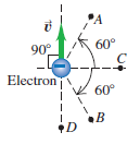
(a). points A and B;
(b). point C;
(c). point D.
Transcribed Image Text:
'A 90 60° Electron 60° •B
> A very long, cylindrical wire of radius R carries a current I0 uniformly distributed across the cross section of the wire. Calculate the magnetic flux through a rectangle that has one side of length W running down the center of the wire and another side
> A conducting rod with length L = 0.200 m, mass m = 0.120 kg, and resistance R = 80.0 Ω moves without friction on metal rails as shown in Fig. 29.11. A uniform magnetic field with magnitude B = 1.50 T is directed into the plane of the figure. The rod is
> A flexible circular loop 6.50 cm in diameter lies in a magnetic field with magnitude 1.35 T, directed into the plane of the page as shown in Fig. P29.53. The loop is pulled at the points indicated by the arrows, forming a loop of zero area in 0.250 s.
> You are shipwrecked on a deserted tropical island. You have some electrical devices that you could operate using a generator but you have no magnets. The earth’s magnetic field at your location is horizontal and has magnitude 8.0 × 10⁻⁵ T, and you decide
> In Fig. P29.51 the loop is being pulled to the right at constant speed v. A constant current I flows in the long wire, in the direction shown. Fig. P29.51: (a). Calculate the magnitude of the net emf a く-r→ b
> An electron and a proton are each moving at 735 km/s in perpendicular paths as shown in Fig. E28.8. At the instant when they are at the positions shown, find the magnitude and direction of (a). the total magnetic field they produce at the origin; (b).
> Two circular loops lie side by side in the same plane. One is connected to a source that supplies an increasing current; the other is a simple closed ring. Is the induced current in the ring in the same direction as the current in the loop connected to t
> Suppose the loop in Fig. P29.50 is Fig. P29.50: (a). rotated about the y-axis; (b). rotated about the x-axis; (c). rotated about an edge parallel to the z-axis. What is the maximum induced emf in each case if A = 600 cm2, A X. 3
> The solenoid is removed from the enclosure and then used in a location where the earth’s magnetic field is 50 µT and points horizontally. A sample of bacteria is placed in the center of the solenoid, and the same current is applied that produced a magnet
> To use a larger sample, the experimenters construct a solenoid that has the same length, type of wire, and loop spacing but twice the diameter of the original. How does the maximum possible magnetic torque on a bacterium in this new solenoid compare with
> What current is needed in the wire so that the magnetic field experienced by the bacteria has a magnitude of 150
> A wide, long, insulating belt has a uniform positive charge per unit area
> Two long, straight conducting wires with linear mass density λ are suspended from cords so that they are each horizontal, parallel to each other, and a distance d apart. The back ends of the wires are connected to each other by a slack, low
> A pair of long, rigid metal rods, each of length 0.50 m, lie parallel to each other on a frictionless table. Their ends are connected by identical, very lightweight conducting springs with unstretched length l0 and force constant k (Fig. P28.78). When a
> You use a tesla meter (a Hall-effect device) to measure the magnitude of the magnetic field at various distances from a long, straight, thick cylindrical copper cable that is carrying a large constant current. To exclude the earth’s mag
> As a summer intern at a research lab, you are given a long solenoid that has two separate windings that are wound close together, in the same direction, on the same hollow cylindrical form. You must determine the number of turns in each winding. The sole
> Positive point charges q = +8.00 µC and q' = +3.00 µC are moving relative to an observer at point P, as shown in Fig. E28.6. The distance d is 0.120 m, v = 4.50 × 10⁶ m/s, and v' = 9.00 × 10⁶ m/s Fig.
> A long, straight, solid cylinder, oriented with its axis in the z-direction, carries a current whose current density is
> In Fig. 29.8, if the angular speed v of the loop is doubled, then the frequency with which the induced current changes direction doubles, and the maximum emf also doubles. Why? Does the torque required to turn the loop change? Explain. Fig. 29.8: (
> Long, straight conductors with square cross section, each carrying current I, are laid side by side to form an infinite current sheet with current directed out of the plane of the page (Fig. P28.74). A second infinite current sheet is a distance d below
> Long, straight conductors with square cross sections and each carrying current I are laid side by side to form an infinite current sheet (Fig. P28.73). The conductors lie in the xy-plane, are parallel to the y-axis, and carry current in the +y-direction.
> A circular loop has radius R and carries current I2 in a clockwise direction (Fig. P28.72). The center of the loop is a distance D above a long, straight wire. What are the magnitude and direction of the current I1 in the wire if the magnetic field at th
> A long, straight, solid cylinder, oriented with its axis in the z-direction, carries a current whose current density is
> The wire shown in Fig. P28.70 is infinitely long and carries a current I. Calculate the magnitude and direction of the magnetic field that this current produces at point P. Fig. P28.70:
> A long, straight wire with a circular cross section of radius R carries a current I. Assume that the current density is not constant across the cross section of the wire, but rather varies as J =
> Calculate the magnetic field (magnitude and direction) at a point P due to a current I = 12.0 A in the wire shown in Fig. P28.68. Segment BC is an arc of a circle with radius 30.0 cm, and point P is at the center of curvature of the arc. Segment DA is an
> Figure P28.67 is a sectional view of two circular coils with radius a, each wound with N turns of wire carrying a current I, circulating in the same direction in both coils. The coils are separated by a distance a equal to their radii. In this configurat
> Several charges enter a uniform magnetic field directed into the page. (a). What path would a positive charge q moving with a velocity of magnitude v follow through the field? (b). What path would a positive charge q moving with a velocity of magnitude
> Two long, parallel wires hang by 4.00-cm-long cords from a common axis (Fig. P28.65). The wires have a mass per unit length of 0.0125 kg/m and carry the same current in opposite directions. What is the current in each wire if the cords hang at an angle o
> The long, straight wire AB shown in Fig. P28.64 carries a current of 14.0 A. The rectangular loop whose long edges are parallel to the wire carries a current of 5.00 A. Find the magnitude and direction of the net force exerted on the loop by the magnetic
> Your physics study partner asks you to consider a parallelplate capacitor that has a dielectric completely filling the volume between the plates. He then claims that Eqs. (29.13) and (29.14) show that the conduction current in the dielectric equals the d
> Two long, straight, parallel wires are 1.00 m apart (Fig. P28.63). The wire on the left carries a current I1 of 6.00 A into the plane of the paper. Fig. P28.63: (a). What must the magnitude and direction of the current I2 be for the net field at poin
> An electric bus operates by drawing direct current from two parallel overhead cables, at a potential difference of 600 V, and spaced 55 cm apart. When the power input to the bus’s motor is at its maximum power of 65 hp, (a). what current does it draw an
> An electron is moving in the vicinity of a long, straight wire that lies along the x-axis. The wire has a constant current of 9.00 A in the -x-direction. At an instant when the electron is at point (0, 0.200 m, 0) and the electron’s velocity is
> A long, straight wire carries a 13.0-A current. An electron is fired parallel to this wire with a velocity of 250 km/s in the same direction as the current, 2.00 cm from the wire. (a). Find the magnitude and direction of the electron’s initial accelerati
> A long, straight wire carries a current of 8.60 A. An electron is traveling in the vicinity of the wire. At the instant when the electron is 4.50 cm from the wire and traveling at a speed of 6.00 × 10⁴ m/s directly toward the wire, what are the magnitude
> Two long, parallel transmission lines, 40.0 cm apart, carry 25.0-A and 75.0-A currents. Find all locations where the net magnetic field of the two wires is zero if these currents are in (a). the same direction and (b). the opposite direction.
> At a particular instant, charge q1 = +4.80 × 10⁻⁶ C is at the point (0, 0.250 m, 0) and has velocity
> An alpha particle (charge +2e) and an electron move in opposite directions from the same point, each with the speed of 2.50 × 10⁵ m/s (Fig. E28.4). Find the magnitude and direction of the total magnetic field these charges produce at point P
> A pair of point charges, q = +8.00 µC and q' = -5.00 µC, are moving as shown in Fig. P28.55 with speeds v = 9.00 × 10⁴ m/s and v' = 6.50 × 10⁴ m/s. When the charges are at the locations shown in the figure, what are the magnitude and direction of (a). t
> The large magnetic fields used in MRI can produce forces on electric currents within the human body. This effect has been proposed as a possible method for imaging “biocurrents” flowing in the body, such as the current that flows in individual nerves. Fo
> Which of following elements is a candidate for MRI? (a). 12C6; (b). 16O8; (c). 40Ca20; (d). 31P15.
> In the situation shown in Fig. 29.18, would it be appropriate to ask how much energy an electron gains during a complete trip around the wire loop with current I'? Would it be appropriate to ask what potential difference the electron moves through during
> If a proton is exposed to an external magnetic field of 2 T that has a direction perpendicular to the axis of the proton’s spin, what will be the torque on the proton? (a). 0; (b). 1.4 × 10⁻²⁶ N ∙ m; (c). 2.8 × 10⁻²⁶ N ∙ m; (d). 0.7 × 10⁻²⁶ N ∙ m.
> A particle with mass m and positive charge q starts from rest at the origin shown in Fig. P27.82. There is a uniform electric field
> A particle with charge 2.15 µC and mass 3.20 × 10⁻¹¹ kg is initially traveling in the +y-direction with a speed v0 = 1.45 × 10⁵ m/s. It then enters a region containing a uniform magnetic field that is directed into,
> You are using a type of mass spectrometer to measure charge-to-mass ratios of atomic ions. In the device, atoms are ionized with a beam of electrons to produce positive ions, which are then accelerated through a potential difference V. (The final speed o
> A circular loop of wire with area A lies in the xy-plane. As viewed along the z-axis looking in the z-direction toward the origin, a current I is circulating clockwise around the loop. The torque produced by an external magnetic field
> The neutron is a particle with zero charge. Nonetheless, it has a nonzero magnetic moment with z-component 9.66 × 10⁻²⁷ A ∙ m2. This can be explained by the internal structure of the neutron. A substantial body of evidence
> It was shown in Section 27.7 that the net force on a current loop in a uniform magnetic field is zero. But what if B S is not uniform? Figure P27.75 shows a square loop of wire that lies in the xy-plane. The loop has corners at (0, 0), (0, L), (L, 0), an
> The lower end of the thin uniform rod in Fig. P27.74 is attached to the floor by a frictionless hinge at point P. The rod has mass 0.0840 kg and length 18.0 cm and is in a uniform magnetic field B = 0.120 T that is directed into the page. The rod is held
> It was shown in Section 27.7 that the net force on a current loop in a uniform magnetic field is zero. The magnetic force on the voice coil of a loudspeaker (see Fig. 27.28) is nonzero because the magnetic field at the coil is not uniform. A voice coil i
> A uniform bar has mass 0.0120 kg and is 30.0 cm long. It pivots without friction about an axis perpendicular to the bar at point a (Fig. P27.72). The gravitational force on the bar acts in the –y-direction. The bar is in a uniform magne
> Example 29.6 discusses the external force that must be applied to the slidewire to move it at constant speed. If there were a break in the left-hand end of the U-shaped conductor, how much force would be needed to move the slidewire at constant speed? As
> The loop of wire shown in Fig. P27.71 forms a right triangle and carries a current I = 5.00 A in the direction shown. The loop is in a uniform magnetic field that has magnitude B = 3.00 T and the same direction as the current in side PQ of the loop. Fi
> A uniform bar of length L carries a current I in the direction from point a to point b (Fig. P27.70). The bar is in a uniform magnetic field that is directed into the page. Consider the torque about an axis perpendicular to the bar at point a that is due
> The rectangular loop of wire shown in Fig. P27.69 has a mass of 0.15 g per centimeter of length and is pivoted about side ab on a frictionless axis. The current in the wire is 8.2 A in the direction shown. Find the magnitude and direction of the magnetic
> The rectangular loop shown in Fig. P27.68 is pivoted about the y-axis and carries a current of 15.0 A in the direction indicated. Fig. P27.68: (a). If the loop is in a uniform magnetic field with magnitude 0.48 T in the +x-direction, find the magnitu
> A long wire carrying 6.50 A of current makes two bends, as shown in Fig. P27.67. The bent part of the wire passes through a uniform 0.280-T magnetic field directed as shown and confined to a limited region of space. Find the magnitude and direction of th
> Figure E27.49 shows a portion of a silver ribbon with z1 = 11.8 mm and y1 = 0.23 mm, carrying a current of 120 A in the +x-direction. The ribbon lies in a uniform magnetic field, in the y-direction, with magnitude 0.95 T. Apply the simplified model of th
> A conducting bar with mass m and length L slides over horizontal rails that are connected to a voltage source. The voltage source maintains a constant current I in the rails and bar, and a constant, uniform, vertical magnetic field
> A plastic circular loop has radius R, and a positive charge q is distributed uniformly around the circumference of the loop. The loop is then rotated around its central axis, perpendicular to the plane of the loop, with angular speed
> One method for determining the amount of corn in early Native American diets is the stable isotope ratio analysis (SIRA) technique. As corn photosynthesizes, it concentrates the isotope carbon-13, whereas most other plants concentrate carbon-12. Overreli
> A 2.60-N metal bar, 0.850 m long and having a resistance of 10.0 Ω, rests horizontally on conducting wires connecting it to the circuit shown in Fig. P27.62. The bar is in a uniform, horizontal, 1.60-T magnetic field and is not attach
> A straight piece of conducting wire with mass M and length L is placed on a frictionless incline tilted at an angle
> In deriving the force on one of the long, current-carrying conductors in Section 28.4, why did we use the magnetic field due to only one of the conductors? That is, why didn’t we use the total magnetic field due to both conductors?
> A mass spectrograph is used to measure the masses of ions, or to separate ions of different masses (see Section 27.5). In one design for such an instrument, ions with mass m and charge q are accelerated through a potential difference V. They then enter a
> Suppose the electric field between the plates in Fig. 27.24 is 1.88 × 10⁴ V/m and the magnetic field in both regions is 0.682 T. If the source contains the three isotopes of krypton, 82Kr, 84Kr, and 86Kr, and the ions are singly charged, fin
> A particle with negative charge q and mass m = 2.58 × 10⁻¹⁵ kg is traveling through a region containing a uniform magnetic field
> You wish to hit a target from several meters away with a charged coin having a mass of 4.25 g and a charge of +2500 µC. The coin is given an initial velocity of 12.8 m/s, and a downward, uniform electric field with field strength 27.5 N/C exists througho
> In a shunt-wound dc motor with the field coils and rotor connected in parallel (Fig. E27.47), the resistance Rf of the field coils is 106 Ω, and the resistance Rr of the rotor is 5.9 Ω. When a potential difference of 120 V is applied to the brushes and t
> In the Bohr model of the hydrogen atom (see Section 39.3), in the lowest energy state the electron orbits the proton at a speed of 2.2 × 10⁶ m/s in a circular orbit of radius 5.3 × 10⁻¹¹ m. (a). What is the orbital period of the electron? (b). If the o
> If two deuterium nuclei (charge +e, mass 3.34 × 10⁻²⁷ kg) get close enough together, the attraction of the strong nuclear force will fuse them to make an isotope of helium, releasing vast amounts of energy. The range of this force is about 10-15 m. This
> A particle with charge 7.26 × 10⁻⁸ C is moving in a region where there is a uniform 0.650-T magnetic field in the +x-direction. At a particular instant, the velocity of the particle has components vx = -1.68 × 10⁴ m/s, vy = -3.11 × 10⁴ m/s, and vz = 5.85
> When a particle of charge q > 0 moves with a velocity of
> The electronics supply company where you work has two different resistors, R1and R2, in its inventory, and you must measure the values of their resistances. Unfortunately, stock is low, and all you have are R1 and R2 in parallel and in series—and you can
> You set up the circuit shown in Fig. 26.20, where C = 5.00 × 10⁻⁶ F. At time t = 0, you close the switch and then measure the charge q on the capacitor as a function of the current i in the resistor. Your results are given in the table: (a
> Suppose you have three long, parallel wires arranged so that in cross section they are at the corners of an equilateral triangle. Is there any way to arrange the currents so that all three wires attract each other? So that all three wires repel each othe
> You connect a number of identical light bulbs to a flashlight battery. (a). What happens to the brightness of each bulb as more and more bulbs are added to the circuit if you connect them (i) in series and (ii) in parallel? (b). Will the battery last l
> You set up the circuit shown in Fig. 26.22a, where R = 196 Ω. You close the switch at time t = 0 and measure the magnitude i of the current in the resistor R as a function of time t since the switch was closed. Your results are shown in Fig.
> A capacitor that is initially uncharged is connected in series with a resistor and an emf source with
> A dc motor with its rotor and field coils connected in series has an internal resistance of 3.2 Ω. When the motor is running at full load on a 120-V line, the emf in the rotor is 105 V. (a). What is the current drawn by the motor from the line? (b). Wh
> In the Bainbridge mass spectrometer (see Fig. 27.24), the magnetic-field magnitude in the velocity selector is 0.510 T, and ions having a speed of 1.82 × 10⁶ m/s pass through undeflected. Fig. 27.24: (a). What is the electric-field magnit
> A 224- Ω resistor and a 589- Ω resistor are connected in series across a 90.0-V line. (a). What is the voltage across each resistor? (b). A voltmeter connected across the 224- Ω resistor reads 23.8 V. Find the voltmeter resistance. (c). Find the readi
> A 2.36-µF capacitor that is initially uncharged is connected in series with a 5.86- Ω resistor and an emf source with
> (See Problem 26.67.) Problem 26.67: Figure P26.67 employs a convention often used in circuit diagrams. The battery (or other power supply) is not shown explicitly. It is understood that the point at the top, labeled “36.0 V,â
> The circuit shown in Fig. P26.74, called a Wheatstone bridge, is used to determine the value of an unknown resistor X by comparison with three resistors M, N, and P whose resistances can be varied. For each setting, the resistance of each resistor is pre
> Point an in Fig. P26.73 is maintained at a constant potential of 400 V above ground. (See Problem 26.67.) Fig. P26.73: (a). What is the reading of a voltmeter with the proper range and with resistance 5.00 × 10⁴Ω whe
> A 6.00-µF capacitor that is initially uncharged is connected in series with a 5.00- resistor and an emf source with
> A 2.00-µF capacitor that is initially uncharged is connected in series with a 6.00-k Ω resistor and an emf source with
> The capacitor in Fig. P26.70 is initially uncharged. The switch S is closed at t = 0. Fig. P26.70: (a). Immediately after the switch is closed, what is the current through each resistor? (b). What is the final charge on the capacitor? R1 = 8.00 N
> Two parallel conductors carrying current in the same direction attract each other. If they are permitted to move toward each other, the forces of attraction do work. From where does the energy come? Does this contradict the assertion in Chapter 27 that m
> A resistor R1 consumes electrical power P1 when connected to an emf
> The 20.0 cm × 35.0 cm rectangular circuit shown in Fig. E27.41 is hinged alongside ab. It carries a clockwise 5.00-A current and is located in a uniform 1.20-T magnetic field oriented perpendicular to two of its sides, as shown. Fig. E27.4
> Figure P26.67 employs a convention often used in circuit diagrams. The battery (or other power supply) is not shown explicitly. It is understood that the point at the top, labeled “36.0 V,” is connected to the positive
> In the circuit shown in Fig. P26.66 all the resistors are rated at a maximum power of 2.00 W. What is the maximum emf
> In the circuit shown in Fig. P26.65, the current in the 20.0-V battery is 5.00 A in the direction shown and the voltage across the 8.00- resistor is 16.0 V, with the lower end of the resistor at higher potential. Find Fig. P26.65: (a). the emf (inclu
> (a). Find the current through the battery and each resistor in the circuit shown in Fig. P26.62. Fig. P26.62: (b). What is the equivalent resistance of the resistor network? R = 1.00 R2 R = 1.00 0 ww | 14.0 3= 2,00 0 V R4 = 2.00 0 1.00 N
> Find the current through each of the three resistors of the circuit shown in Fig. P26.61. The emf sources have negligible internal resistance. Fig. P26.61: 20.0 V + 5.00 N ww $2.00 C4.00_+ Ω 36.0 V + 14.0 V
> What must the emf

