Question: A beam of length L is designed
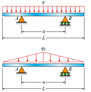
A beam of length L is designed to support a uniform load of intensity q (see figure). If the supports of the beam are placed at the ends, creating a simple beam, the maximum bending moment in the beam is qL2/8. However, if the supports of the beam are moved symmetrically toward the middle of the beam (as shown), the maximum bending moment is reduced.
(a) Determine the distance a between the supports so that the maximum bending moment in the beam has the smallest possible numerical value. Draw the shear-force and bending-moment diagrams for this condition.
(b) Repeat part (a) if the uniform load is replaced with a triangularly distributed load with peak intensity q0 = q at mid-span (see Fig. b).
Transcribed Image Text:
B a -L- go a- -
> A flat bar of width b and thickness t has a hole of diameter d drilled through it (see figure). The hole may have any diameter that will fit within the bar. What is the maximum permissible tensile load Pmax if the allowable tensile stress in the material
> The flat bars shown in parts a and b of the figure are subjected to tensile forces P = 2.5 kN. Each bar has thickness t = 5.0 mm. (a) For the bar with a circular hole, determine the maximum stresses for hole diameters d = 12 mm and d = 20 mm if the width
> The flat bars shown in parts a and b of the figure are subjected to tensile forces P = 3.0 kips. Each bar a has thickness t = 0.25 in. (a) For the bar with a circular hole, determine the maximum stresses for hole diameters d = 1 in. and d = 2 in. if the
> A simply supported beam (L = 4.5 m) must support mechanical equipment represented as a distributed load with intensity q = 30 kN/m acting over the middle segment of the beam (see figure). Select the most economical W-shape steel beam to support the loads
> Draw the shear-force and bending-moment diagrams for a cantilever beam AB carrying a uniform load of intensity q over one-half of its length (see figure). A B L 2
> A simple beam AB is subjected to a counterclockwise couple of moment Mo acting at distance a from the left-hand support (see figure). Draw the shear force and bending-moment diagrams for this beam. Also draw the shear-force and bending-moment diagrams if
> Draw the shear-force and bending-moment diagrams for a simple beam AB supporting two equal concentrated loads P (see figure). Repeat if the left-hand load is upward and the right-hand load is downward. |P B
> The centrifuge shown in the figure rotates in a horizontal plane (the x-y plane) on a smooth surface about the z axis (which is vertical) with an angular acceleration α. Each of the two arms has a weight w per unit length and supports a wei
> The simply supported beam ABCD is loaded by a weight W = 27 kN through the arrangement shown in the figure part a. The cable passes over a small frictionless pulley at B and is attached at E to the end of the vertical arm. (a) Calculate the axial force N
> Frame ABC has a moment release just left of joint B. Find axial force N, shear force V, and moment M at the top of column AB. Write variables N, V, and M in terms of variables P and L. P Moment release L/4 L/4 C B N, V, Mat L L/2 P L/2 A
> Frame ABCD carries two concentrated loads (2P at C and P at D, see figure) and also a linearly varying distributed load on AB. Find expressions for shear force V and moment M at x = L/3 of beam AB in terms of peak load intensity qo, force P, and beam len
> A cable with force P is attached to a frame at D and runs over a frictionless pulley at B. Find expressions for shear force V and moment M at x = L/3 of beam AB. L/3 C Di Cable L/3 L/3 B A 2L/3 V, Mat L/3
> Find expressions for shear force V and moment M at x = L/2 of beam AB in structure (a) Express V and M in terms of peak load intensity qo and beam length variable L. Repeat for structure (b) but find V and M at mid-span of member BC. g0 A 4L/5 B L/
> A cable with force P is attached to a frame at A and runs over a frictionless pulley at D. Find expressions for shear force V and moment M at x = L/2 of beam BC. Cable L'2 B L/2 L/2 C V, Mat L/2 L/2 A
> A cantilever beam AB having rectangular cross sections with varying width bx and varying height hx is subjected to a uniform load of intensity q (see figure). If the width varies linearly with x according to the equation bx = bB x/L, how should the heigh
> Find expressions for shear force V and moment M at x = L/2 of beam BC. Express V and M in terms of peak load intensity qo and beam length variable L. 90 D L/2 B L/2 L/2 C V, Mat L/2 L/2 go
> Find expressions for shear force V and moment M at x = xo of beam AB in terms of peak load intensity qo and beam length variable L. Let x0 = 2L/3. 90 90 B A V, Mat xo
> Find expressions for shear force V and moment M at x = xo of beam AB in terms of peak load intensity qo and beam length variable L. Let x0 = L/2. q(x) = 1 90 В A V, Mat xo
> Find expressions for shear force V and moment M at x = 2L/3 of beam (a) in terms of peak load intensity qo and beam length variable L. Repeat for beam (b). 9, at L/2 A B 9, at L/2 V, Mat 2L/3 X. RA Rg Beam (a) 9, at Z 9о at L/2 A B V, M at 2L/3 L-
> Find expressions for shear force V and moment M at x = 2L/3 of beam (a) in terms of peak load intensity qo and beam length variable L. Repeat for beam (b) but at x = L/2. 9o at L/2 A B V, Mat 2L/3 L- RA R3 Beam (a) 9o at 2L/3 A B V, Mat L/2 -L- RA
> Find expressions for shear force V and moment M at mid-span of beam AB in terms of peak load intensity qo and beam length variables a and L Let a = 5L/6. B C V, Mat L/2 a L-
> Find shear (V) and moment (M) at x = 3L/4 for the beam shown in Fig. a. Let MA = 24 kNm? P = 48 kN, L = 6 m, and qo = 8 kN/m. Repeat for the beam in Fig. b (first solve for the reaction moment at fixed support A). MA Р. B L/4- L/2 L/2 L/4 (а) P B M
> Beam ABCD represents a reinforced- concrete foundation beam that supports a uniform load of intensity q1 = 3500 lb/ft (see figure). Assume that the soil pressure on the underside of the beam is uniformly distributed with intensity q2. (a) Find the shear
> A simply supported beam AB supports a trapezoid ally distributed load (see figure). The intensity of the load varies linearly from 50 kN/m at support A to 25 kN/m at support B. Calculate the shear force V and bending moment M at the midpoint of the beam.
> A beam ABCD with a vertical arm CE is supported as a simple beam at A and D (see figure part a) A cable passes over a small pulley that is attached to the arm at E. One end of the cable is attached to the beam at point B. (a) What is the force P in the c
> A simple beam ABC having rectangular cross sections with constant height h and varying width bx supports a concentrated load P acting at the midpoint (see figure). How should the width bx vary as a function of x in order to have a fully stressed beam? (E
> Under cruising conditions, the distributed load acting on the wing of a small airplane has the idealized variation shown in the figure. Calculate the shear force V and bending moment M at 4 m from the tip of the wing. a) WojciechBeczyns
> A curved bar ABC is subjected to loads in the form of two equal and opposite forces P, as shown in the figure. The axis of the bar forms a semicircle of radius r. Determine the axial force N, shear force V, and bending moment M acting at a cross section
> At a full draw, an archer applies a pull of 130 N to the bowstring of the bow shown in the figure. Determine the bending moment at the midpoint of the bow. 70° 1400 mm 350 mm
> The beam ABCD shown in the figure has overhangs at each end and carries a uniform load of intensity q (Fig. a). For what ratio b/L will the bending moment at the midpoint of the beam be zero? Repeat for a triangular load with peak
> The beam ABC shown in the figure is simply supported at A and B and has an overhang from B to C. The loads consist of a horizontal force P1 = 4.0 kN acting at the end of a vertical arm and a vertical force P2 = 8.0 kN acting at the end of the
> Consider the beam with an overhang shown in the figure. (a) Determine the shear force V and bending moment M at a cross section located 18 ft from the left-hand end A. (b) Find the required magnitude of load intensity q acting on the right half of member
> Calculate the shear force V and bending moment M at a cross section located just right of the 4 kN load on the cantilever beam AB shown in the figure. |4.0 kN 1.5 kN/m B -1.0 m-1.0 m- 2.0 m-
> Determine the shear force V and bending moment M at the midpoint of the beam with overhangs (see figure). Note that one load acts downward and the other upward, and clockwise moments Pb are applied at each support. Repeat if moments Pb are moved to the e
> Determine the shear force V and bending moment M just right of the 6 kN load on the simple beam AB shown in the figure. 16.0 kN 2.0 kN/m B 0.5 m -1.0 m-1.0 m→ - 2.0 m - 4.0 m-
> Calculate the shear force V and bending moment M at a cross section just to the right of the 800 lb load acting on the simple beam AB shown in the figure. 800 1b 1600 1b B -30 in. 50 in. → 40 in. 120 in.
> A cantilever beam AB with rectangular cross sections of a constant width b and varying height hx is subjected to a uniform load of intensity q (see figure). How should the height hx vary as a function of x (measured from the free end of the beam) in orde
> The plane frame shown in the figure is part of an elevated freeway system. Supports at A and D are fixed, but there are moment releases at the base of both columns (AB and DE) as well as in column BC and at the end of beam BE. Find all support reactions;
> A plane frame (see figure) consists of column AB and beam BC that carries a triangular distributed load (see figure part a). Support A is fixed, and there is a roller support at C. Beam BC has a shear release just right of joint B. (a) Find the support r
> Beam ABC is supported by a tie rod CD as shown. Two configurations are possible: pin support at A and downward triangular load on AB or pin at B and upward load on AB. Which has the larger maximum moment? First, find all support reactions; th
> The inclined beam represents a ladder with the following applied loads: the weight (W) of the house painter and the distributed weight (w) of the ladder itself. (a) Find support reactions at A and B; then plot axial force (N), shear (V), and moment (M) d
> A simple beam AB supports two connected wheel loads 3P and 2P that are a distance d apart (see figure). The wheels may be placed at any distance x from the left-hand support of the beam. (Assume P = 12 kN, d = 2 m, and L = 15 m.) (a) Determine the distan
> A compound beam (see figure) has an shear release just to the left of C and a moment release just to the right of C. A plot of the moment diagram is provided below the beam for applied load P at B and triangular distributed loads w(x) on segments BC and
> A compound beam (see figure) has an internal moment release just to the left of B and a shear release just to the right of C. Reactions have been computed at A, C, and D and are shown in the figure. First, confirm the reaction expressions using statics;
> The shear-force diagram for a beam is shown in the figure. Assuming that no couples act as loads on the beam, determine the forces acting on the beam and draw the bending-moment diagram. 450 lb, 50 lb -150 lb --150 lb -350 lb 16 ft 4 ft 4 ft
> The shear-force diagram for a simple beam is shown in the figure. Determine the loading on the beam and draw the bending-moment diagram, assuming that no couples act as loads on the beam. 6.25 kN 6.25 kN V 1.25 kN --8.75 kN 1 m 1 m 1 m 1 m
> Draw the shear-force and bending-moment diagrams for beam AB with a sliding support at A and an elastic support with spring constant k at B acted upon by two different load cases: (a) A distributed load with linear variation and maximum intensity qo (see
> Refer to the tapered cantilever beam of solid circular cross section shown in Fig. 5-26 of Example 5-9. (a) Considering only the bending stresses due to the load P, determine the range of values of the ratio dB/dA for which the maximum normal stress occu
> The compound beam ABCDE shown in the figure consists of two beams (AD and DE) joined by a hinged connection (or moment release) at D. The moment release can transmit a shear force but not a bending moment. Draw the shear-force and bending-moment diagrams
> A beam with simple supports is subjected to a trapezoid ally distributed load (see figure). The intensity of the load varies from 1.0 kN/m at support A to 2.5 kN/m at support B. (a) Draw the shear-force and bending-moment diagrams for this be
> The simple beam ACB shown in the figure is subjected to a triangular load of maximum intensity qo = 200 lb/ft at a = 8 ft and a concentrated moment M = 400 lb-ft at A. (a) Draw the shear-force and bending-moment diagrams for this beam. (b) Find the value
> Beams ABC and CD are supported at A, C, and D and are joined by a hinge (or moment release) just to the left of C. The support at A is a sliding support (hence reaction Ay = 0 for the loading shown below). Find all support reactions; then plot shear (V)
> A beam ABCD with a vertical arm CE is supported as a simple beam at A and D (see figure). AÂ cable passes over a small pulley that is attached to the arm at E. One end of the cable is attached to the beam at point B. The tensile force in the c
> The beam ABCD shown in the figure has overhangs that extend in both directions for a distance of 4.2Â m from the supports at B and C, which are 1.2 m apart. Draw the shear-force and bending-moment diagrams for this overhanging beam. 10 kN
> Two beams (see figure) are loaded the same and have the same support conditions. However, the location of internal axial, shear, and moment releases is different for each beam (see figures). Which beam has the larger maximum moment? First, find support r
> A simple beam AB is loaded by two segments of uniform load and two horizontal and vertical forces acting at the ends of a vertical arm (see figure). Draw the shear-force and bending-moment diagrams for this beam. 3 kN 8 kN 4 kN/m 4 kN/m 1 m A B 1m 8
> The beam ABC shown in the figure is simply supported at A and B and has an overhang from B to C. Draw the shear-force and bending-moment diagrams for beam ABC. Note: Disregard the widths of the beam and vertical arm and use centerline dimensions when mak
> The spokes in a large flywheel are modeled as beams fixed at one end and loaded by a force P and a couple Mo at the other (see figure). The cross sections of the spokes are elliptical with major and minor axes (height and width, respectively) having the
> A rectangular beam with notches and a hole (see figure) has dimensions h = 5.5 in, h1 = 5 in., and width b = 1.6 in. The beam is subjected to a bending moment M = 130 kip-in, and the maximum allowable bending stress in the material (steel) is σ
> The three beams in the figure have the same loading. However, one has a moment release just to the left of C, the second has a shear release just to the right of C, and the third has an axial release just to the left of C. Which beam has the largest maxi
> Consider the two beams shown in the figures. Which beam has the larger maximum moment? First, find support reactions; then plot axial force (N), shear (V), and moment (M) diagrams for both beams. Label all critical N, V, and M values and also the distanc
> Beam ABC with an overhang at one end supports a partial uniform load of intensity 12 kN/m and a concentrated moment of magnitude 4 kN m at C (see figure). Draw the shear-force and bending-moment diagrams for this beam. 4 kN - m 12 kN/m B -1.6 m- -1.
> Beam ABC has simple supports at A and B, an overhang BC and the distributed loading shown in the figure. Draw the shear-force and bending-moment diagrams for this beam. 50 lb/in. 25 lb/in. 25 lb/in. A C B -72 in. -48 in-
> The cantilever beam AB shown in the figure is subjected to a triangular load acting over one-half of its length and a concentrated load acting at the free end. Draw the shear-force and bending-moment diagrams for this beam. 2.0 kN/m 2.5 kN iB A -2 m
> A cantilever beam AB supports a couple and a concentrated load, as shown in the figure. Draw the shear-force and bending-moment diagrams for this beam. 200 lb 400 1b-ft B 5 ft - 5 ft
> The beam AB shown in the figure supports a uniform load of intensity 3000 N/m acting over half the length of the beam. The beam rests on a foundation that produces a uniformly distributed load over the entire length. (a) Draw the shear-force and bending-
> The simple beam AB supports a triangular load of maximum intensity qo = 10 lb/in. acting over one-half of the span and a concentrated load P = 80 lb acting at mid span (see figure). Draw the shear-force and bending-moment diagrams for this beam. 90
> Draw the shear-force and bending-moment diagrams for a cantilever beam AB acted upon by two different load cases. (a) A distributed load with linear variation and maximum intensity qo (see figure part a). (b) A distributed load with parabolic variation a
> Beam ABCD is simply supported at B and C and has overhangs at each end (see Fig. a). The span length is L and each overhang has length L/3. A uniform load of intensity q acts along the entire length of the beam. (a) Draw the shear-force and b
> A tapered cantilever beam AB with rectangular cross sections is subjected to a concentrated load P = 50 lb and a couple Mo = 800 lb-in acting at the free end (see figure part a). The width b of the beam is constant and equal to 1.0 in., but the height va
> A beam ABC is simply supported at A and B and has an overhang BC (see figure). The beam is loaded by two forces P and a clockwise couple of moment Pa at D that act through the arrangement shown. (a) Draw the shear-force and bending-moment diagrams for be
> A simply supported beam ABC is loaded at the end of a bracket BDE (see figure). Draw axial-force, shear-force, and bending-moment diagrams for ABC. 2P L/3 D E P L/3 L/3 B 2L/3
> A simply supported beam ABC is loaded by a vertical load P acting at the end of a bracket BDE (see figure). (a) Draw the shear-force and bending-moment diagrams for beam ABC. (b) Now assume that load P at E is directed to the right. The vertical dimensio
> A simple beam AB subjected to couples M1 and 3M1 acting at the third points is shown in the figure. Draw the shear-force and bending-moment diagrams for this beam. M1 3M1 A B L 3 3
> The simple beam AB shown in the figure is subjected to a concentrated load P and a clockwise couple M1 = PL/3 acting at the third points. Draw the shear-force and bending-moment diagrams for this beam. PL M1 = IP 3 B L 3
> Cantilever beam AB carries an upward uniform load of intensity q1 from x = 0 to L/2 (see Fig. a) and a downward uniform load of intensity q from x = L/2 to L. (a) Find q1 in terms of q if the resulting moment at A is zero. Draw V and M diagra
> The cantilever beam AB shown in the figure is subjected to a concentrated load P at the midpoint and a counterclockwise couple of moment M1 = PL/4 at the free end. Draw the shear-force and bending-moment diagrams for this beam. PL M1 = 4 A |B L 2 2
> A stepped shaft consisting of solid circular segments having diameters D1 = 2.0 in. and D2 = 2.4 in. (see figure) is subjected to torques T. The radius of the fillet is R = 0.1 in. If the allowable shear stress at the stress concentration is 6000 psi, wh
> A hollow circular tube having an inside diameter of 10.0 in. and a wall thickness of 1.0 in. (see figure) is subjected to a torque T = 1200 kip-in. Determine the maximum shear stress in the tube using (a) the approximate theory of thin-walled tubes, and
> A solid circular bar of steel (G = 11.4 × 10⁶ psi) with length L = 30 in. and diameter d = 1.75 in. is subjected to pure torsion by torques T acting at the ends (see figure). (a) Calculate the amount of strain energy U stored in the bar when
> A solid circular bar ABCD with fixed supports is acted upon by torques To and 2To at the locations shown in the figure. (a) Obtain a formula for the maximum angle of twist φmax of the bar. (b) What is φmax if the applied torque To a
> A generator shaft in a small hydroelectric plant turns at 120 rpm and delivers 50 hp (see figure). (a) If the diameter of the shaft is d = 3.0 in., what is the maximum shear Ï„max in the shaft? (b) If the shear stress is limited to 4000 psi, wh
> A circular copper bar with diameter d = 3 in. is subjected to torques T = 30 kip-in. at its ends. Find the maximum shear, tensile, and compressive stresses in the tube and their corresponding strains. Assume that G = 6000 ksi. d= 3 in. T T -L = 80 i
> A solid copper bar of circular cross section has length L = 1.25 m and shear modulus of elasticity G = 45 GPa. The bar is designed to carry a 250 Nm? torque acting at the ends. If the allowable shear stress is 30 MPa and the allowable angle of twist betw
> Two tubes (AB, BC) of the same material are connected by three pins (pin diameter = dp) just left of B as shown in the figure. Properties and dimensions for each tube are given in the figure. Torque 2T is applied at x = 2L/5 and uniformly distributed tor
> A non prismatic bar ABC with a solid circular cross section is loaded by distributed torques (see figure). The intensity of the torques, that is, the torque per unit distance, is denoted t(x) and varies linearly from zero at A to a maximum value To/L at
> A magnesium-alloy wire of diameter d = 4 mm and length L rotates inside a flexible tube in order to open or close a switch from a remote location (see figure). A torque T is applied manually (either clockwise or counterclockwise) at end B, thus twisting
> A prismatic bar AB with a solid circular cross section (diameter d) is loaded by a distributed torque (see figure). The intensity of the torque, that is, the torque per unit distance, is denoted t(x) and varies linearly from a maximum value tA at end A t
> A prismatic bar AB of length L and solid circular cross section (diameter d) is loaded by a distributed torque of constant intensity t per unit distance (see figure). (a) Determine the maximum shear stress Ï„max in the bar. (b) Determine the an
> A mountain-bike rider going uphill applies torque T = Fd (F = 15 lb, d = 4 in.) to the end of the handlebars ABCD by pulling on the handlebar extenders DE. Consider the right half of the handlebar assembly only (assume the bars are fixed at the fork at&A
> A wood beam ABC with simple supports at A and B and an overhang BC has height h = 300 mm (see figure). The length of the main span of the beam is L = 3.6 m and the length of the overhang is L/3 = 1.2m. The beam supports a concentrated load P = 31 8 kN at
> For the thin non prismatic steel pipe of constant thickness t and variable diameter d shown with applied torques at joints 2 and 3, determine the following. (a) Find the reaction moment R1. (b) Find an expression for twist rotation φ3 at join
> A uniformly tapered aluminum-alloy tube AB with a circular cross section and length L is shown in the figure. The outside diameters at the ends are dA and dB = 2dA. A hollow section of length L/2 and constant thickness t = dA/10 is cast into the tube and
> The non prismatic, cantilever circular bar shown has an internal cylindrical hole from 0 to x, so the net polar moment of inertia of the cross section for segment 1 is (7/8) Ip. Torque T is applied at x and torque T/2 is applied at x= L. Assume that G is
> The bar shown in the figure is tapered linearly from end A to end B and has a solid circular cross section. The diameter at the smaller end of the bar is dA = 25 mm and the length is L = 300 mm. The bar is made of steel with shear modulus of elasticity G
> A tapered bar AB with a solid circular cross section is twisted by torques T = 36,000 lb-in (see figure). The diameter of the bar varies linearly from dA at the left-hand end to dB at the right-hand end. The bar has length L = 4.0 ft and is made of an al
> A tapered bar AB with a solid circular cross section is twisted by torques T (see figure). The diameter of the bar varies linearly from dA at the left-hand end to dB at the right-hand end. (a) Confirm that the angle of twist of the tapered bar is (b) For
> Four gears are attached to a circular shaft and transmit the torques shown in the figure. The allowable shear stress in the shaft is 10,000 psi. (a) What is the required diameter d of the shaft if it has a solid cross section? (b) What is the required ou
> Two sections of steel drill pipe, joined by bolted flange plates at B, are being tested to assess the adequacy of both the pipes. In the test, the pipe structure is fixed at A, a concentrated torque of 500 kNm? is applied at x = 0.5 m, and uniformly dist
> A solid steel shaft ABCDE turns freely in bearings at points A and E. The shaft is driven by the gear at C, which applies a torque T2 = 325 lb-ft. Gears at B and D are driven by the shaft and have resisting torques T1 = 200 lb-ft and T3 = 125 lb-ft, resp

