Question: A prismatic bar AB with a solid
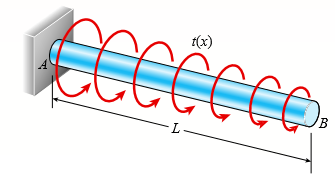
A prismatic bar AB with a solid circular cross section (diameter d) is loaded by a distributed torque (see figure). The intensity of the torque, that is, the torque per unit distance, is denoted t(x) and varies linearly from a maximum value tA at end A to zero at end B. Also, the length of the bar is L and the shear modulus of elasticity of the material is G.
(a) Determine the maximum shear stress Ï„max in the bar.
(b) Determine the angle of twist φ between the ends of the bar.
Transcribed Image Text:
t(x) L-
> Beam ABC is supported by a tie rod CD as shown. Two configurations are possible: pin support at A and downward triangular load on AB or pin at B and upward load on AB. Which has the larger maximum moment? First, find all support reactions; th
> The inclined beam represents a ladder with the following applied loads: the weight (W) of the house painter and the distributed weight (w) of the ladder itself. (a) Find support reactions at A and B; then plot axial force (N), shear (V), and moment (M) d
> A simple beam AB supports two connected wheel loads 3P and 2P that are a distance d apart (see figure). The wheels may be placed at any distance x from the left-hand support of the beam. (Assume P = 12 kN, d = 2 m, and L = 15 m.) (a) Determine the distan
> A compound beam (see figure) has an shear release just to the left of C and a moment release just to the right of C. A plot of the moment diagram is provided below the beam for applied load P at B and triangular distributed loads w(x) on segments BC and
> A compound beam (see figure) has an internal moment release just to the left of B and a shear release just to the right of C. Reactions have been computed at A, C, and D and are shown in the figure. First, confirm the reaction expressions using statics;
> The shear-force diagram for a beam is shown in the figure. Assuming that no couples act as loads on the beam, determine the forces acting on the beam and draw the bending-moment diagram. 450 lb, 50 lb -150 lb --150 lb -350 lb 16 ft 4 ft 4 ft
> The shear-force diagram for a simple beam is shown in the figure. Determine the loading on the beam and draw the bending-moment diagram, assuming that no couples act as loads on the beam. 6.25 kN 6.25 kN V 1.25 kN --8.75 kN 1 m 1 m 1 m 1 m
> Draw the shear-force and bending-moment diagrams for beam AB with a sliding support at A and an elastic support with spring constant k at B acted upon by two different load cases: (a) A distributed load with linear variation and maximum intensity qo (see
> Refer to the tapered cantilever beam of solid circular cross section shown in Fig. 5-26 of Example 5-9. (a) Considering only the bending stresses due to the load P, determine the range of values of the ratio dB/dA for which the maximum normal stress occu
> The compound beam ABCDE shown in the figure consists of two beams (AD and DE) joined by a hinged connection (or moment release) at D. The moment release can transmit a shear force but not a bending moment. Draw the shear-force and bending-moment diagrams
> A beam of length L is designed to support a uniform load of intensity q (see figure). If the supports of the beam are placed at the ends, creating a simple beam, the maximum bending moment in the beam is qL2/8. However, if the supports of the beam are mo
> A beam with simple supports is subjected to a trapezoid ally distributed load (see figure). The intensity of the load varies from 1.0 kN/m at support A to 2.5 kN/m at support B. (a) Draw the shear-force and bending-moment diagrams for this be
> The simple beam ACB shown in the figure is subjected to a triangular load of maximum intensity qo = 200 lb/ft at a = 8 ft and a concentrated moment M = 400 lb-ft at A. (a) Draw the shear-force and bending-moment diagrams for this beam. (b) Find the value
> Beams ABC and CD are supported at A, C, and D and are joined by a hinge (or moment release) just to the left of C. The support at A is a sliding support (hence reaction Ay = 0 for the loading shown below). Find all support reactions; then plot shear (V)
> A beam ABCD with a vertical arm CE is supported as a simple beam at A and D (see figure). AÂ cable passes over a small pulley that is attached to the arm at E. One end of the cable is attached to the beam at point B. The tensile force in the c
> The beam ABCD shown in the figure has overhangs that extend in both directions for a distance of 4.2Â m from the supports at B and C, which are 1.2 m apart. Draw the shear-force and bending-moment diagrams for this overhanging beam. 10 kN
> Two beams (see figure) are loaded the same and have the same support conditions. However, the location of internal axial, shear, and moment releases is different for each beam (see figures). Which beam has the larger maximum moment? First, find support r
> A simple beam AB is loaded by two segments of uniform load and two horizontal and vertical forces acting at the ends of a vertical arm (see figure). Draw the shear-force and bending-moment diagrams for this beam. 3 kN 8 kN 4 kN/m 4 kN/m 1 m A B 1m 8
> The beam ABC shown in the figure is simply supported at A and B and has an overhang from B to C. Draw the shear-force and bending-moment diagrams for beam ABC. Note: Disregard the widths of the beam and vertical arm and use centerline dimensions when mak
> The spokes in a large flywheel are modeled as beams fixed at one end and loaded by a force P and a couple Mo at the other (see figure). The cross sections of the spokes are elliptical with major and minor axes (height and width, respectively) having the
> A rectangular beam with notches and a hole (see figure) has dimensions h = 5.5 in, h1 = 5 in., and width b = 1.6 in. The beam is subjected to a bending moment M = 130 kip-in, and the maximum allowable bending stress in the material (steel) is σ
> The three beams in the figure have the same loading. However, one has a moment release just to the left of C, the second has a shear release just to the right of C, and the third has an axial release just to the left of C. Which beam has the largest maxi
> Consider the two beams shown in the figures. Which beam has the larger maximum moment? First, find support reactions; then plot axial force (N), shear (V), and moment (M) diagrams for both beams. Label all critical N, V, and M values and also the distanc
> Beam ABC with an overhang at one end supports a partial uniform load of intensity 12 kN/m and a concentrated moment of magnitude 4 kN m at C (see figure). Draw the shear-force and bending-moment diagrams for this beam. 4 kN - m 12 kN/m B -1.6 m- -1.
> Beam ABC has simple supports at A and B, an overhang BC and the distributed loading shown in the figure. Draw the shear-force and bending-moment diagrams for this beam. 50 lb/in. 25 lb/in. 25 lb/in. A C B -72 in. -48 in-
> The cantilever beam AB shown in the figure is subjected to a triangular load acting over one-half of its length and a concentrated load acting at the free end. Draw the shear-force and bending-moment diagrams for this beam. 2.0 kN/m 2.5 kN iB A -2 m
> A cantilever beam AB supports a couple and a concentrated load, as shown in the figure. Draw the shear-force and bending-moment diagrams for this beam. 200 lb 400 1b-ft B 5 ft - 5 ft
> The beam AB shown in the figure supports a uniform load of intensity 3000 N/m acting over half the length of the beam. The beam rests on a foundation that produces a uniformly distributed load over the entire length. (a) Draw the shear-force and bending-
> The simple beam AB supports a triangular load of maximum intensity qo = 10 lb/in. acting over one-half of the span and a concentrated load P = 80 lb acting at mid span (see figure). Draw the shear-force and bending-moment diagrams for this beam. 90
> Draw the shear-force and bending-moment diagrams for a cantilever beam AB acted upon by two different load cases. (a) A distributed load with linear variation and maximum intensity qo (see figure part a). (b) A distributed load with parabolic variation a
> Beam ABCD is simply supported at B and C and has overhangs at each end (see Fig. a). The span length is L and each overhang has length L/3. A uniform load of intensity q acts along the entire length of the beam. (a) Draw the shear-force and b
> A tapered cantilever beam AB with rectangular cross sections is subjected to a concentrated load P = 50 lb and a couple Mo = 800 lb-in acting at the free end (see figure part a). The width b of the beam is constant and equal to 1.0 in., but the height va
> A beam ABC is simply supported at A and B and has an overhang BC (see figure). The beam is loaded by two forces P and a clockwise couple of moment Pa at D that act through the arrangement shown. (a) Draw the shear-force and bending-moment diagrams for be
> A simply supported beam ABC is loaded at the end of a bracket BDE (see figure). Draw axial-force, shear-force, and bending-moment diagrams for ABC. 2P L/3 D E P L/3 L/3 B 2L/3
> A simply supported beam ABC is loaded by a vertical load P acting at the end of a bracket BDE (see figure). (a) Draw the shear-force and bending-moment diagrams for beam ABC. (b) Now assume that load P at E is directed to the right. The vertical dimensio
> A simple beam AB subjected to couples M1 and 3M1 acting at the third points is shown in the figure. Draw the shear-force and bending-moment diagrams for this beam. M1 3M1 A B L 3 3
> The simple beam AB shown in the figure is subjected to a concentrated load P and a clockwise couple M1 = PL/3 acting at the third points. Draw the shear-force and bending-moment diagrams for this beam. PL M1 = IP 3 B L 3
> Cantilever beam AB carries an upward uniform load of intensity q1 from x = 0 to L/2 (see Fig. a) and a downward uniform load of intensity q from x = L/2 to L. (a) Find q1 in terms of q if the resulting moment at A is zero. Draw V and M diagra
> The cantilever beam AB shown in the figure is subjected to a concentrated load P at the midpoint and a counterclockwise couple of moment M1 = PL/4 at the free end. Draw the shear-force and bending-moment diagrams for this beam. PL M1 = 4 A |B L 2 2
> A stepped shaft consisting of solid circular segments having diameters D1 = 2.0 in. and D2 = 2.4 in. (see figure) is subjected to torques T. The radius of the fillet is R = 0.1 in. If the allowable shear stress at the stress concentration is 6000 psi, wh
> A hollow circular tube having an inside diameter of 10.0 in. and a wall thickness of 1.0 in. (see figure) is subjected to a torque T = 1200 kip-in. Determine the maximum shear stress in the tube using (a) the approximate theory of thin-walled tubes, and
> A solid circular bar of steel (G = 11.4 × 10⁶ psi) with length L = 30 in. and diameter d = 1.75 in. is subjected to pure torsion by torques T acting at the ends (see figure). (a) Calculate the amount of strain energy U stored in the bar when
> A solid circular bar ABCD with fixed supports is acted upon by torques To and 2To at the locations shown in the figure. (a) Obtain a formula for the maximum angle of twist φmax of the bar. (b) What is φmax if the applied torque To a
> A generator shaft in a small hydroelectric plant turns at 120 rpm and delivers 50 hp (see figure). (a) If the diameter of the shaft is d = 3.0 in., what is the maximum shear Ï„max in the shaft? (b) If the shear stress is limited to 4000 psi, wh
> A circular copper bar with diameter d = 3 in. is subjected to torques T = 30 kip-in. at its ends. Find the maximum shear, tensile, and compressive stresses in the tube and their corresponding strains. Assume that G = 6000 ksi. d= 3 in. T T -L = 80 i
> A solid copper bar of circular cross section has length L = 1.25 m and shear modulus of elasticity G = 45 GPa. The bar is designed to carry a 250 Nm? torque acting at the ends. If the allowable shear stress is 30 MPa and the allowable angle of twist betw
> Two tubes (AB, BC) of the same material are connected by three pins (pin diameter = dp) just left of B as shown in the figure. Properties and dimensions for each tube are given in the figure. Torque 2T is applied at x = 2L/5 and uniformly distributed tor
> A non prismatic bar ABC with a solid circular cross section is loaded by distributed torques (see figure). The intensity of the torques, that is, the torque per unit distance, is denoted t(x) and varies linearly from zero at A to a maximum value To/L at
> A magnesium-alloy wire of diameter d = 4 mm and length L rotates inside a flexible tube in order to open or close a switch from a remote location (see figure). A torque T is applied manually (either clockwise or counterclockwise) at end B, thus twisting
> A prismatic bar AB of length L and solid circular cross section (diameter d) is loaded by a distributed torque of constant intensity t per unit distance (see figure). (a) Determine the maximum shear stress Ï„max in the bar. (b) Determine the an
> A mountain-bike rider going uphill applies torque T = Fd (F = 15 lb, d = 4 in.) to the end of the handlebars ABCD by pulling on the handlebar extenders DE. Consider the right half of the handlebar assembly only (assume the bars are fixed at the fork at&A
> A wood beam ABC with simple supports at A and B and an overhang BC has height h = 300 mm (see figure). The length of the main span of the beam is L = 3.6 m and the length of the overhang is L/3 = 1.2m. The beam supports a concentrated load P = 31 8 kN at
> For the thin non prismatic steel pipe of constant thickness t and variable diameter d shown with applied torques at joints 2 and 3, determine the following. (a) Find the reaction moment R1. (b) Find an expression for twist rotation φ3 at join
> A uniformly tapered aluminum-alloy tube AB with a circular cross section and length L is shown in the figure. The outside diameters at the ends are dA and dB = 2dA. A hollow section of length L/2 and constant thickness t = dA/10 is cast into the tube and
> The non prismatic, cantilever circular bar shown has an internal cylindrical hole from 0 to x, so the net polar moment of inertia of the cross section for segment 1 is (7/8) Ip. Torque T is applied at x and torque T/2 is applied at x= L. Assume that G is
> The bar shown in the figure is tapered linearly from end A to end B and has a solid circular cross section. The diameter at the smaller end of the bar is dA = 25 mm and the length is L = 300 mm. The bar is made of steel with shear modulus of elasticity G
> A tapered bar AB with a solid circular cross section is twisted by torques T = 36,000 lb-in (see figure). The diameter of the bar varies linearly from dA at the left-hand end to dB at the right-hand end. The bar has length L = 4.0 ft and is made of an al
> A tapered bar AB with a solid circular cross section is twisted by torques T (see figure). The diameter of the bar varies linearly from dA at the left-hand end to dB at the right-hand end. (a) Confirm that the angle of twist of the tapered bar is (b) For
> Four gears are attached to a circular shaft and transmit the torques shown in the figure. The allowable shear stress in the shaft is 10,000 psi. (a) What is the required diameter d of the shaft if it has a solid cross section? (b) What is the required ou
> Two sections of steel drill pipe, joined by bolted flange plates at B, are being tested to assess the adequacy of both the pipes. In the test, the pipe structure is fixed at A, a concentrated torque of 500 kNm? is applied at x = 0.5 m, and uniformly dist
> A solid steel shaft ABCDE turns freely in bearings at points A and E. The shaft is driven by the gear at C, which applies a torque T2 = 325 lb-ft. Gears at B and D are driven by the shaft and have resisting torques T1 = 200 lb-ft and T3 = 125 lb-ft, resp
> A square wood platform is 8 ft × 8ft in area and rests on masonry walls (see figure). The deck of the platform is constructed of 2-in. nominal thickness tongue-and-groove planks (actual thickness 1.5 in.; see Appendix G) supported on two 8-f
> A shaft with a solid, circular cross section consisting of two segments is shown in part a of the figure. The left-hand segment has a diameter of 80Â mm and length of 1.2 m; the right-hand segment has a diameter of 60 mm and length of 0.9 m. S
> A hollow tube ABCDE constructed of monel metal is subjected to five torques acting in the directions shown in the figure. The magnitudes of the torques are T1 = 1000lb-in, T2 = T4 = 500 lb-in, and T3 = T5 = 800 lb-in. The tube has an outside diameter of
> A solid, circular bar ABC consists of two segments, as shown in the figure. One segment has a diameter of d1 = 56 mm and length of L1 = 1.45 m; the other segment has a diameter of d2 = 48 mm and length of L2 = 1.2 m. What is the allowable torque Tallow i
> A stepped shaft ABCD consisting of solid circular segments is subjected to three torques, as shown in the figure. The torques have magnitudes of 12.5Â kip-in., 9.8 kip-in., and 9.2 kip-in. The length of each segment is 25 in. and the diameters
> A circular tube of outer diameter d3 = 70 mm and inner diameter d2 = 60 mm is welded at the right hand end to a fixed plate and at the left-hand end to a rigid end plate (see figure). A solid, circular bar with a diameter of d1 = 40 mm is inside of, and
> A stepped shaft ABC consisting of two solid circular segments is subjected to torques T1 and T2 acting in opposite directions, as shown in the figure. The larger segment of the shaft has a diameter of d1 = 2.25 in and length L1 = 30 in; the smaller segme
> A solid steel bar of circular cross section has diameter d = 2.5 in, L = 60 in, and shear modulus of elasticity G = 11.5 × 10⁶ psi. The bar is subjected to torques T = 300 lb-ft at the ends. Calculate the angle of twist between the ends. Wha
> A circular aluminum tube subjected to pure torsion by torques T (see figure) has an outer radius r2 equal to 1.5 times the inner radius r1. (a) If the maximum shear strain in the tube is measured as 400 × 10-6 rad, what is the shear strain g
> Solve the preceding problem if the length L = 56 in, the inner radius r1 = 1.25 in, the angle of twist is 0.5 °, and the allowable shear strain is 0.0004 rad. Data from Problem 4: A circular steel tube of length L = 1.0m is loaded in torsio
> A circular steel tube of length L = 1.0m is loaded in torsion by torques T (see figure). (a) If the inner radius of the tube is r1 = 45 mm and the measured angle of twist between the ends is 0.5°, what is the shear strain γ1 (in ra
> A simply supported wood beam of rectangular cross section and span length 1.2 m carries a concentrated load P at mid span in addition to its own weight (see figure). The cross section has width 140 mm and height 240 mm. The weight density of the wood is
> A copper rod of length L = 18.0in. is to be twisted by torques T (see figure) until the angle of rotation between the ends of the rod is 3.0°. (a) If the allowable shear strain in the copper is 0.0006 rad, what is the maximum permissible diame
> A plastic bar of diameter d = 56 mm is to be twisted by torques T (see figure) until the angle of rotation between the ends of the bar is 4.0°. (a) If the allowable shear strain in the plastic is 0.012 rad, what is the minimum permissible length of the b
> A circular tube is subjected to torque T at its ends. The resulting maximum shear strain in the tube is 0.005. Calculate the minimum shear strain in the tube and the shear strain at the median line of the tube section. T T -Median line -2.5 in.- 3 i
> A circular tube of inner radius r1 and outer radius r2 is subjected to a torque produced by forces P = 900 lb (see figure part a). The forces have their lines of action at a distance b = 5.5 in from the outside of the tube. (a) If the allowable shear str
> A hollow aluminum tube used in a roof structure has an outside diameter d2 = 104 mm and an inside d1 = 82 mm (see figure). The tube is 2.75 m long, and the aluminum has shear modulus G = 28GPa. (a) If the tube is twisted in pure torsion by torques acting
> A solid brass bar of diameter d = 1.25 in is subjected to torques T1, as shown in part a of the figure. The allowable shear stress in the brass is 12 ksi. (a) What is the maximum permissible value of the torques T1? (b) If a hole of diameter 0.625 in. is
> A vertical pole of solid, circular cross section is twisted by horizontal forces P = 5 kN acting at the ends of a rigid horizontal arm AB (see figure part a). The distance from the outside of the pole to the line of action of each force is c = 125 mm (se
> A vertical pole of solid, circular cross section is twisted by horizontal forces P = 1100 lb acting at the ends of a rigid horizontal arm AB (see figure part a). The distance from the outside of the pole to the line of action of each force is c = 5.0 in
> Solve the preceding problem if the shaft has an outer diameter d2 = 150 mm and inner diameter d1 = 100 mm. Also, the steel has a shear modulus of elasticity G = 75 GPa, and the applied torque is 16 kNm? Data from Problem 15: A hollow steel shaft used
> A hollow steel shaft used in a construction auger has an outer diameter d2 = 6.0 in and inner diameter d1 = 4.5 in (see figure). The steel has a shear modulus of elasticity G = 11.0 × 10⁶psi. For an applied torque of 150 kip-in., determine t
> A wood beam AB on simple supports with span length equal to 10 ft is subjected to a uniform load of intensity 125 lb/ft acting along the entire length of the beam, a concentrated load of magnitude 7500 lb acting at a point 3 ft from the right-hand suppor
> The steel axle of a large winch on an ocean liner is subjected to a torque of 1.65 kNm? (see figure). (a) What is the minimum required diameter dmin if the allowable shear stress is 48 MPa and the allowable rate of twist is 0.75°/m? (Assume th
> Three identical circular disks A, B, and C are welded to the ends of three identical solid circular bars (see figure). The bars lie in a common plane and the disks lie in planes perpendicular to the axes of the bars. The bars are welded at their intersec
> A propeller shaft for a small yacht is made of a solid steel bar 104 mm in diameter. The allowable stress in shear is 48 MPa, and the allowable rate of twist is 2.0° in 3.5 meters. (a) Assuming that the shear modulus of elasticity is G = 80 GP
> A circular tube of aluminum is subjected to torsion by torques T applied at the ends (see figure). The bar is 24 in. long, and the inside and outside diameters are 1.25 in. and 1.75 in., respectively. It is determined by measurement that the angle of twi
> A high-strength steel drill rod used for boring a hole in the earth has a diameter of 0.5 in. (see figure). The allowable shear stress in the steel is 40Â ksi and the shear modulus of elasticity is 11,600 ksi. (a) What is the minimum required
> An aluminum bar of solid circular cross section is twisted by torques T acting at the ends (see figure). The dimensions and shear modulus of elasticity are L = 1.4 m, d = 32 mm, and G = 28 GPa. (a) Determine the torsional stiffness of the bar. (b) If the
> While removing a wheel to change a tire, a driver applies forces P = 25 lb at the ends of two of the arms of a lug wrench (see figure). The wrench is made of steel with shear modulus of elasticity G = 11.4 × 10⁶ psi. Each arm of the wrench i
> When drilling a hole in a table leg, a furniture maker uses a hand-operated drill (see figure) with a bit of diameter d = 4.0 mm. (a) If the resisting torque supplied by the table leg is equal to 0.3 Nm? what is the maximum shear stress in the drill bit?
> A prospector uses a hand-powered winch (see figure) to raise a bucket of ore in his mine shaft. The axle of the winch is a steel rod of diameter d = 0.625 in. Also, the distance from the center of the axle to the center of the lifting rope is b = 4.0 in.
> A laminated plastic beam of square cross section is built up by gluing together three strips, each 10 mm × 30 mm in cross section (see figure). The beam has a total weight of 3.6 N and is simply supported with span length L = 360 mm. Conside
> A copper tube with circular cross section has length L = 1.25 m, thickness t = 2 mm, and shear modulus of elasticity G = 45 GPa. The bar is designed to carry a 300 Nm? torque acting at the ends. If the allowable shear stress is 25 MPa and the allowable a
> Repeat Problem 1, but now use a circular tube with outer diameter do = 2.5 in. and inner diameter di = 1.5 in. Data from Problem 1: A solid steel bar of circular cross section has diameter d = 2.5 in, L = 60 in, and shear modulus of elasticity G = 11.
> Two circular aluminum pipes of equal length L = 24 in. are loaded by torsional moments T (see figure). Pipe 1 has outside and inside diameters d2 = 3 in and d1 = 2.5 in, respectively. Pipe 2 has a constant outer diameter of d2 along its entire length&Aci
> A solid aluminum bar (G = 2 7 GPa) of diameter d = 40 mm is subjected to torques T = 300 Nm? acting in the directions shown in the figure. (a) Determine the maximum shear, tensile, and compressive stresses in the bar and show these stresses on sketches o
> A solid steel bar (G = 11.8 × 10⁶ psi) of diameter d = 2.0 in. is subjected to torques T = 8.0 kip-in. acting in the directions shown in the figure. (a) Determine the maximum shear, tensile, and compressive stresses in the bar and show these
> An aluminum tube has inside diameter d1 = 50 mm, shear modulus of elasticity G = 27 GPa, v = 0.33, and torque T = 4.0 kNm? The allowable shear stress in the aluminum is 50 MPa, and the allowable normal strain is 900 × 10-6. (a) Determine the required out

