Question: A brass plate with a modulus of
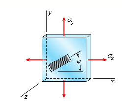
A brass plate with a modulus of elasticity E = 16 × 106 psi and Poisson’s ratio v = 0.34 is loaded in biaxial stress by normal stresses σx and σy (see figure). A strain gage is bonded to the plate at an angle ∅ = 35°.
If the stress sx is 10,700 psi and the strain measured by the gage is ε = 390 × 1026, what is the maximum in-plane shear stress (τmax)xy and shear strain (γmax)xy? What is the maximum shear strain (γmax)xz in the xz plane? What is the maximum shear strain (γmax)yz in the yz plane?
Transcribed Image Text:
y 2.
> A rubber sheet in biaxial stress is subjected to tensile stresses σx = 270 Pa and σy = 144 Pa. The corresponding strains in the sheet are εx = 0.0002 and εy = 0.000015. Determine Poisson’s
> The normal stress on an elastomeric rubber pad in a test machine is σy = -100 psi (see figure). Assume E = 312 psi and shear modulus G = 105 psi. (a) Calculate the strains in the pad in the x, y, and z directions. (b) Calculate the unit volume
> A circle of a diameter d = 200 mm is etched on a brass plate (see figure). The plate has dimensions of 400 × 400 × 20 mm. Forces are applied to the plate, producing uniformly distributed normal stresses σx = 59 MPa an
> A simple log bridge in a remote area consists of two parallel logs with planks across them (see figure). The logs are Douglas fir with an average diameter 300Â mm. A truck moves slowly across the bridge, which spans 2.5 m. Assume that the weig
> A rectangular beam with semicircular notches, as shown in part b of the figure, has dimensions h = 0.88 in. and h1 = 0.80 in. The maximum allowable bending stress in the metal beam is σmax = 60 ksi, and the bending moment is M = 600 lb-in. Det
> Solve the preceding problem for an aluminum plate with b = 10 in, t = 0.75 in., E = 10,600 ksi, v = 0.33, Px = 96 kips, Py = 24 kips, and V = 18 kips. For part (b) of Problem 12, assume that the required strain energy stored is 640 in.-lb. In part (c), t
> A square plate of a width b and thickness t is loaded by normal forces Px and Py and by shear forces V, as shown in the figure. These forces produce uniformly distributed stresses acting on the side faces of the plate. (a) Calculate the change â
> A 4.0 in. cube of concrete (E = 4.5 × 10⁶ psi, v = 0.2) is compressed in biaxial stress by means of a framework that is loaded as shown in the figure. Assuming that each load F equals 25 kips, determine the change âˆ&#
> A brass cube of 48 mm on each edge is compressed in two perpendicular directions by forces P = 160 kN (see figure). (a) Calculate the change ∆V in the volume of the cube and the strain energy U stored in the cube, assuming E = 100 GPa a
> Solve the preceding problem for an aluminum plate with σx = 12,000 psi (tension), σy = 23000 psi (compression), dimensions 20 × 30 × 0.5 in, E = 10.5 × 10⁶ psi, and v = 0.33. Data from Proble
> A rectangular plate in biaxial stress (see figure) is subjected to normal stresses σx = 67 MPa (tension) and σy = -23 MPa (compression). The plate has dimensions 400 × 550 × 20 mm and is made of steel with
> Solve the preceding problem for a steel plate with σx = 11,600 psi (tension), σy = -5700 psi (compression), εx = 450 × 1026 (elongation), and εy = -310 × 1026 (shortening). Data
> A cast-iron plate in biaxial stress is subjected to tensile stresses σx = 31 MPa and σy = 17 MPa (see figure). The corresponding strains in the plate are εx = 240 × 1026 and εy = 85 Ã
> Assume that the normal strains εx and εy for an element in plane stress (see figure) are measured with strain gages. (a) Obtain a formula for the normal strain εz in the z direction in terms of εx, &Ici
> An element of a material is subjected to plane stresses as shown in the figure. The stresses σx, σy, and τxy are 10 MPa, –15 MPa, and 5 MPa, respectively. Assume E = 200 GPa and v = 0.3. (a) Calculate th
> Calculate the maximum shear stress Ï„max in the web of the T-beam shown in the figure if b = 10 in, t = 0.5 in, h = 7 in., h1 = 6.2 in., and the shear force V = 5300 lb. hi b-
> The state of stress on an element of material is shown in the figure. Calculate the unit volume change of the element if the stresses σx and σy are –20 ksi and 10 ksi, respectively. Assume E = 10,600 ks
> Solve the preceding problem if the thickness of the steel plate is t = 12 mm , the gage readings are εx = 530 × 10-6− (elongation) and εy – 2210 × 10-6 (shortening),
> A solid bronze sphere (volume modulus of elasticity K = 14.5 × 10⁶ psi) is suddenly heated around its outer surface. The tendency of the heated part of the sphere to expand produces uniform tension in all directions at the center of the sphere. If the st
> A solid steel sphere (E = 210 GPa, v = 0.3) is subjected to hydrostatic pressure p such that its volume is reduced by 0.4%. (a) Calculate the pressure p. (b) Calculate the volume modulus of elasticity K for the steel. (c) Calculate the strain energy U st
> A solid spherical ball of magnesium alloy (E = 6.5 × 1026 psi, v = 0.35) is lowered into the ocean to a depth of 8000 ft. The diameter of the ball is 9.0 in. (a) Determine the decrease ∆d in diameter, the decrease ∆V in volume, and the strain energy U of
> A copper bar with a square cross section is inserted into a square rigid tube as shown in the figure. The length of the copper bar is 1.2 m and the area of the cross section is 300 mm2. The bar is subjected to a force P that applies a uniformly distribut
> A rubber cube R of a side L = 3 in and cross- sectional area A = 9 in2 is compressed inside a steel cube S by a force F = 5 lb that applies uniformly distributed pressure to the rubber. Assume E = 0.3 ksi and n=v = 0.45. (a) Calculate the lateral pressur
> A block R of rubber is confined between plane parallel walls of a steel block S (see figure). A uniformly distributed pressure p0 is applied to the top of the rubber block by a force F. (a) Derive a formula for the lateral pressure p between the rubber a
> A rubber cylinder R of length L and cross- sectional area A is compressed inside a steel cylinder S by a force F that applies a uniformly distributed pressure to the rubber (see figure). (a) Derive a formula for the lateral pressure p between the rubber
> Solve the preceding problem if the material is nylon. (a) Find the bulk modulus K for the nylon if the following stress and strain data is known: normal stresses are σx = 3.9 MPa, σy = 3.2MPa, and σz = 1.8 MPa ; and norma
> The T-beam shown in the figure has cross-sectional dimensions: b = 210 mm, t = 16 mm, h = 300 mm, and h1 = 280 mm. The beam is subjected to a shear force V = 68 kN. Determine the maximum shear stress Ï„max in the web of the beam. hi b-
> An element of aluminum is subjected to triaxial stress (see figure). (a) Find the bulk modulus K for the aluminum if the following stress and strain data are known: normal stresses are σx = 5200 psi (tension), σy = 4750 psi (compres
> Solve the preceding problem if the cube is granite (E = 80 GPa, v = 0.25) with dimensions a = 89 mm and compressive strains εx = 690 × 1026 and εy = εz = 255 × 1026. For part (e) of Problem
> A cube of cast iron with sides of length a = 4.0 in. (see figure) is tested in a laboratory under triaxial stress. Gages mounted on the testing machine show that the compressive strains in the material are εx = -225 × 1026 and &
> An element of aluminum in the form of a rectangular parallelepiped (see figure) of dimensions a = 5.5 in, b = 4.5 in, and c = 3.5 in is subjected to triaxial stresses σx = 12,500 psi, σy = 25000 psi, and sz = 21400 psi acting on the
> An element of aluminum is subjected to triaxial stresses. Calculate the strains in the element in x, y, and z directions if the stresses σx, σy, and σz are –20 MPa, 28 MPa, and –18 MPa,
> Solve Problem 14 by using Mohr’s circle for plane strain. Data from Problem 14: Solve the preceding problem for the following data: εx = 21120 × 1026, εy = 2430 × 1026 , γ
> Solve Problem 13 by using Mohr’s circle for plane strain. Data from Problem 13: An element of material in plane strain (see figure) is subjected to strains εx = 480 × 1026, εy = 70 ×
> Solve Problem 12 by using Mohr’s circle for plane strain. Data from Problem 12: Solve the preceding problem for the following strains: εx = 120 × 1026, εy = -450 × 1026, and Î&
> Solve Problem 11 by using Mohr’s circle for plane strain. Data from Problem 11: The strains for an element of material in plane strain (see figure) are as follows: εx = 480 × 1026, εy = 140 &Atil
> A hollow aluminum box beam has the square cross section shown in the figure. Calculate the maximum and minimum shear stresses Ï„max and Ï„min in the webs of the beam due to a shear force V = 28 k. 1.0 in. 1.0 in. 12 in.
> Solve Problem 10 by using Mohr’s circle for plane strain. Data from Problem 10: Solve the preceding problem for the following data: εx = 190 × 1026, εy = -230 × 1026, γxy
> Solve Problem 9 by using Mohr’s circle for plane strain. Data from Problem 9: An element of material subjected to plane strain (see figure) has strains of εx = 280 × 1026, εy = 420 ×
> The strains on the surface of an experimental device made of pure aluminum (E = 70 GPa, v = 0.33) and tested in a space shuttle were measured by means of strain gages. The gages were oriented as shown in the figure, and the measured strains were Î&
> On the surface of a structural component in a space vehicle, the strains are monitored by means of three strain gages arranged as shown in the figure. During a certain maneuver, the following strains were recorded: εa = 1100 × 1
> A 60° strain rosette, or delta rosette, consists of three electrical-resistance strain gages arranged as shown in the figure. Gage A measures the normal strain εa in the direction of the x axis. Gages B and C measure the strains &
> A solid circular bar with a diameter of d = 1.25 in is subjected to an axial force P and a torque T (see figure). Strain gages A and B mounted on the surface of the bar give readings εA = 140 × 1026 and εB = 260 &At
> A 45° strain rosette (see figure) mounted on the surface of an automobile frame gives the following readings: gage A = 310 × 1026; gage B = 180 × 1026; and gage C = -160 × 1026. Determine the principal st
> During a test of an airplane wing, the strain gage readings from a 45° rosette (see figure) are as follows: gage A = 520 × 1026 ; gage B = 360 × 1026; and gage C = -80 × 1026. Determine the principal stra
> A hollow steel box beam has the rectangular cross section shown in the figure. Determine the maximum allowable shear force V that may act on the beam if the allowable shear stress is 36 MPa. 20 mm 10 mm 10 mm 450 20 Įmm 200 mm
> Solve the preceding problem for the following data: σx = -150 MPa, σy = -210 MPa, τxy = -16 MPa, and θ = 50°. The material is brass with E = 100 GPa and v = 0.34. Data from Problem 17: An elemen
> An element in plane stress is subjected to stresses σx = -8400 psi, σy = 1100 psi, and τxy = -1700 psi (see figure). The material is aluminum with modulus of elasticity E = 10,000 ksi and Poisson’s ratio
> Solve the preceding problem if the plate is made of aluminum with E = 72 GPa and Poisson’s ratio v = 0.33. The plate is loaded in biaxial stress with normal stress σx = 79 MPa, angle ∅ = 18°, and
> Solve the preceding problem for the following data: εx = 21120 × 1026, εy = 2430 × 1026 , γxy = 780 × 1026, and θ = 45°. Data from Problem 13: An elem
> An element of material in plane strain (see figure) is subjected to strains εx = 480 × 1026, εy = 70 × 1026, and γxy = 420 × 1026. Determine the following quantities: (a) the st
> Solve the preceding problem for the following strains: εx = 120 × 1026, εy = -450 × 1026, and γxy = -360 × 1026. Data from Problem 11: The strains for an element of material
> The strains for an element of material in plane strain (see figure) are as follows: εx = 480 × 1026, εy = 140 × 1026, and γxy = -350 × 1026. Determine the principal strains and
> Solve the preceding problem for the following data: εx = 190 × 1026, εy = 230 × 1026, γxy = 160 × 1026, and θ = 40°. Data from Problem 9: An element o
> An element of material subjected to plane strain (see figure) has strains of εx = 280 × 1026, εy = 420 × 1026, and γxy = 150 × 1026. Calculate the strains for an element oriente
> A simple beam with an overhang supports a uniform load of intensity q = 1200 lb/ft and a concentrated P = 3000 lb load at 8 ft to the right of A and also at C (see figure). The uniform load includes an allowance for the weight of the beam. The allowable
> Solve the preceding problem if b = 225 mm, εx = 845 × 1026, and εy = 211 × 1026. Data from Problem 7: A thin square plate in biaxial stress is subjected to stresses σx and σy, a
> A thin square plate in biaxial stress is subjected to stresses σx and σy, as shown in part a of the figure. The width of the plate is b = 12.0 in Measurements show that the normal strains in the x and y directions are ε
> An element of material in plain strain has the following strains: εx = 0.002 and εy = 0.0015. (a) Determine the principal strains of the element. (b) Determine the maximum shear strain of the element. Confirm the solution using
> An element of material in plain strain has the following strains: εx = -0.001 5 and εy = 0.0015. (a) Determine the strains for an element oriented at an angle θ = 25°. (b) Find the principal strains of th
> An element of aluminum is subjected to triaxial stresses. Calculate the strains in the element in x, y, and z directions if the stresses σx, σy, and σz are –2000 psi, 3500 psi, and 2700 psi, respectively
> A bridge girder AB on a simple span of length L = 14 m supports a distributed load of maximum intensity q at mid-span and minimum intensity q/2 at supports A and B that includes the weight of the girder (see figure). The girder is constructed of three pl
> An element in uniaxial stress is subjected to tensile stresses σx = 14,250 psi, as shown in the figure. Using Mohr’s circle, determine the following. (a) The stresses acting on an element oriented at a counterclockwise angle
> The stresses acting on an element are σx = 750 psi, σy = 600 psi, and τxy = 400 psi. Determine the principal stresses and show them on a sketch of a properly oriented element. To
> A rectangular plate of dimensions 125 mm × 75 mm is subjected to tensile stress σx = 67 kPa and compressive stress σy. If it is known that the normal stress along the diagonal t–t is σt = &a
> At a point on the web of a girder on an overhead bridge crane in a manufacturing facility, the stresses are known to be σx = -4300 psi, σy = 1700 psi, and τxy = 3100 psi. A stress element located at the same point in the
> The surface of an airplane wing is subjected to plane stress with normal stresses σx and σy and shear stress τxy, as shown in the figure. At a counterclockwise angle θ = 32° from the x axis, the no
> A gusset plate on a truss bridge is in plane stress with normal stresses σx and σy and shear stress Ï„xy, as shown in the figure. At counterclockwise angles θ = 32° and θ = 78Â&de
> Solve the preceding problem for the element shown in the figure. Data from Problem 21: An element in plane stress from the frame of a racing car is oriented at a known angle θ (see figure). On this inclined element, the normal and shear s
> An element in plane stress from the frame of a racing car is oriented at a known angle θ (see figure). On this inclined element, the normal and shear stresses have the magnitudes and directions shown in the figure. Determine the normal and s
> Solve the preceding problem for σx = 11 MPa and σy = -20 MPa (see figure). Data from Problem 19: At a point on the surface of an elliptical exercise machine, the material is in biaxial stress with sx = 1400 psi and σy
> A cantilever beam AB of length L = 6.5 ft supports a trapezoidal distributed load of peak intensity q, and minimum intensity q/2, that includes the weight of the beam (see figure). The beam is a steel W12 × 14 wide-flange shape. Calculate th
> At a point on the surface of an elliptical exercise machine, the material is in biaxial stress with σx = 1400 psi and σy = -900 psi, as shown in the figure part a. The figure part b shows an inclined plane aa cut through the same po
> Repeat the previous problem using σx = 12 MPa. Data from Problem 17: A simply supported beam is subjected to point load P at mid-span. The normal stress on an element at mid-span is known to be σx = 1.5 ksi. Determine the element
> A simply supported beam is subjected to point load P at mid-span. The normal stress on an element at mid-span is known to be σx = 1.5 ksi. Determine the element stresses if it is rotated through angle θ = -45°. Show the
> Solve the preceding problem for a plate of dimensions 100 mm × 250 mm subjected to a compressive stress of -2.5 MPa in the long direction and a tensile stress of 12.0 MPa in the short direction (see figure). Data from Problem 15: A rectan
> A rectangular plate of dimensions 3.0in. × 5.0 in is formed by welding two triangular plates (see figure). The plate is subjected to a tensile stress of 500 psi in the long direction and a compressive stress of 350 psi in the short direction
> Repeat the previous problem using θ = -40° and stresses on the rotated element: σx1 = 70 MPa, σy1 = -82 MPa, and τx1y1 = -35 MPa. Data from Problem 13: Two steel rods are welded together (see fi
> Two steel rods are welded together (see figure); the seam is oriented at angle θ = -40°. The stresses on the rotated element are σx1 = 10 ksi, σy1 = -12 ksi, and τx1y1 = -5 ksi. Find the state of p
> Solve the preceding problem if the normal and shear stresses acting on the element are σx = 2100 kPa, σy = 300 kPa, and τxy = -560 kPa, and the seam is oriented at an angle of 22.5° to the element. Data from
> The polyethylene liner of a settling pond is subjected to stresses σx = 350 psi, σy = 112 psi, and τxy = 120 psi, as shown by the plane-stress element in the figure part a. Determine the normal and shear stresses acting o
> Solve the preceding problem if the normal and shear stresses acting on element B are -56 MPa, -17 MPa, and 27 MPa (in the directions shown in the figure) and the angle is 40° (clockwise). Data from Problem 9: The stresses acting on element
> Dimensions of cross section: b = 120 mm, t = 7mm, h = 350 mm, h1 = 330 mm, and V = 60 kN. Data for Problem 6: A wide-flange beam (see figure) is subjected to a shear force V. Using the dimensions of the cross section, calculate the moment of inertia an
> The stresses acting on element B (see figure part a) on the web of a wide-flange beam are found to be -14,500 psi in compression in the horizontal direction and -2530 psi in compression in the vertical direction (see figure part b). Also, shear stresses
> An element in plane stress on the fuselage of an airplane (figure part a) is subjected to compressive stresses with a magnitude of 42 MPa in the horizontal direction and tensile stresses with a magnitude of 9.5 MPa in the vertical direction (see figure p
> The cross section of an unbalanced wide flange beam is shown in the figure. Derive the following formula for the distance e from the centerline of the web to the shear center S: Also, check the formula for the special cases of a channel section (b1 = 0 a
> The cross section of an unbalanced wide flange beam is shown in the figure. Derive the following formula for the distance h1 from the centerline of one flange to the shear center S: Also, check the formula for the special cases of a T-beam (b2 = t2 = 0)
> Calculate the distance e from the centerline of the web of a C 310 × 45 channel section to the shear center S (see figure). Note: For purposes of analysis, consider the flanges to be rectangles with thickness tf equal to the average flange t
> Determine the plastic moment MP for a beam having the cross section shown in the figure if σY = 210 MPa. 120 150 mm mm Z- 250 mm 30 mm
> A wide-flange beam with an unbalanced cross section has the dimensions shown in the figure. Determine the plastic moment MP if σY = 36 ksi. 10 in. 0.5 in. z- 7 in. 0.5 in. 0.5 in. -5 in. -
> A singly symmetric beam with a T-section (see figure) has cross-sectional dimensions b = 140 mm, a = 190.8mm, tw = 6.99 mm, and tf = 11.2mm. Calculate the plastic modulus Z and the shape factor f. a
> A W 10 × 60 wide-flange beam is subjected to a bending moment M of such magnitude that the flanges yield but the web remains linearly elastic. (a) Calculate the magnitude of the moment M if the yield stress is σY = 36 ksi. (b) What percent of the moment
> Solve the preceding problem for a box beam with dimensions h = 400 mm, h1 = 360 mm, b = 200 mm, and b1 = 160 mm, and with yield stress σY = 220 MPa. Data from Problem 15: The hollow box beam shown in the figure is subjected to a bending mom
> Wide-flange shape, W18 × 71; V = 21 k. Data for Problem 5: A wide-flange beam (see figure) is subjected to a shear force V. Using the dimensions of the cross section, calculate the moment of inertia and then determine the following quantit
> The hollow box beam shown in the figure is subjected to a bending moment M of such magnitude that the flanges yield but the webs remain linearly elastic. (a) Calculate the magnitude of the moment M if the dimensions of the cross section are h = 15 in ,h1
> Solve the preceding problem for a box beam with dimensions h = 200 mm, h1 = 160 mm, b = 150 mm, and b1 = 130 mm. Assume that the beam is constructed of steel with yield stress σY = 220 MPa. Data from Problem 13: A hollow box beam with heigh
> A hollow box beam with height h = 9.5 in, inside height h1 = 8.0 in, width b = 5.25 in, and inside width b1 = 4.5 in is shown in the figure. Assuming that the beam is constructed of steel with yield stress σY = 42 ksi, calculate the yield mome
> Solve the preceding problem for a box beam with dimensions h = 0.5 m, b = 0.18 m, and t = 22 mm. The yield stress of the steel is 210 MPa. Data from Problem 11: A hollow box beam with height h = 16 in, width b = 8 in, and constant wall thickness t = 0
> A hollow box beam with height h = 16 in, width b = 8 in, and constant wall thickness t = 0.75 in is shown in the figure. The beam is constructed of steel with yield stress σY = 32 ksi. Determine the yield moment MY, plastic moment MP, and shap
> Solve the preceding problem for a W 410 × 85 wide-flange beam. Assume that σY = 250 MPa. Obtain the cross-sectional dimensions and section modulus of the beam in Appendix F. Data from Problem 9: Determine the yield moment MY, plastic moment MP, and sha

