Question: Repeat Problem 4, but now include the
Repeat Problem 4, but now include the weight of the bar. See Table 1 in Appendix I for the weight density of steel.
Data from Problem 4:
A vertical bar consists of three prismatic segments A1, A2, and A3 with cross-sectional areas of 6000 mm2, 5000 mm2, and 4000 mm2, respectively. The bar is made of steel with E = 200 GPa. Calculate the displacements at points B, D, and E. Ignore the weight of the bar.
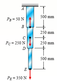
Table 1:
Transcribed Image Text:
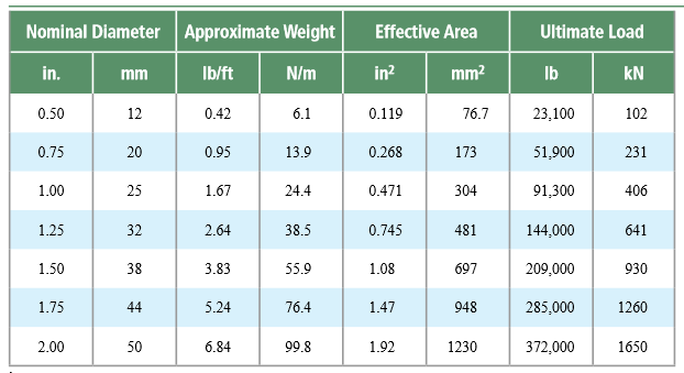
A 500 mm P3 = 50 N B 250 mm C Pc = 250 N 250 mm D 500 mm E PE = 350 N Nominal Diameter Approximate Weight Effective Area Ultimate Load in. mm Ib/ft N/m in? mm? Ib kN 0.50 12 0.42 6.1 0.119 76.7 23,100 102 0.75 20 0.95 13.9 0.268 173 51,900 231 1.00 25 1.67 24.4 0.471 304 91,300 406 1.25 32 2.64 38.5 0.745 481 144,000 641 1.50 38 3.83 55.9 1.08 697 209,000 930 1.75 44 5.24 76.4 1.47 948 285,000 1260 2.00 50 6.84 99.8 1.92 1230 372,000 1650
> A hollow wood beam with plywood webs has the cross-sectional dimensions shown in the figure. The plywood is attached to the flanges by means of small nails. Each nail has an allowable load in shear of 30 lb. Find the maximum allowable spacing s of the na
> A stepped bar ACB with circular cross sections is held between rigid supports and loaded by an axial force P at mid length (see figure). The diameters for the two parts of the bar are d1 = 20 mm and d2 = 25 mm, and the material is elastoplastic with yiel
> Two identical bars AB and BC support a vertical load P (see figure). The bars are made of steel having a stress-strain curve that may be idealized as elastoplastic with yield stress σY. Each bar has cross-sectional area A. Determine the yield
> An aluminum bar subjected to tensile forces P has a length L = 150 in. and cross-sectional area A = 2.0 in2 The stress-strain behavior of the aluminum may be represented approximately by the bilinear stress-strain diagram shown in the figure. Calculate t
> A prismatic bar in tension has a length L = 2.0m and cross-sectional area A = 249 mm2. The material of the bar has the stress-strain curve shown in the figure. Determine the elongation d of the bar for each of the following axial loads: P = 10 kN, 20 kN,
> A hollow circular tube T of a length L = 15 in is uniformly compressed by a force P acting through a rigid plate (see figure). The outside and inside diameters of the tube are 3.0 and 2.75 in., respectively. A concentric solid circular bar B of 1.5 in. d
> Two cables, each having a length L of approximately 40 m, support a loaded container of weight W (see figure). The cables, which have an effective cross- sectional area A = 48.0mm2 and effective modulus of elasticity E = 160 GPa, are identical except tha
> The structure shown in the figure consists of a horizontal rigid bar ABCD supported by two steel wires: one of length L and the other of length 3L/4. Both wires have cross-sectional area A and are made of elastoplastic material with yield stress Ï&#
> Two wood box beams (beams A and B) have the same outside dimensions (200 mm × 360 mm) and the same thickness (t = 2 0mm) throughout, as shown in the figure. Both beams are formed by nailing, with each nail having an allowable shear load of 2
> A rigid bar ACB is supported on a fulcrum at C and loaded by a force P at end B (see figure). Three identical wires made of an elastoplastic material (yield stress σY and modulus of elasticity E) resist the load P. Each wire has cross-sectiona
> A circular steel rod AB with a diameter d = 0.60 in is stretched tightly between two supports so that (initially) the tensile stress in the rod is 10 ksi (see figure). An axial force P is then applied to the rod at an intermediate location C. (a) Determi
> Five bars, each having a diameter of 10 mm, support a load P as shown in the figure. Determine the plastic load PP if the material is elastoplastic with yield stress σY = 250 MPa. トー6一一6一6→6→ 26
> The symmetric truss ABCDE shown in the figure is constructed of four bars and supports a load P at joint E. Each of the two outer bars has a cross-sectional area of 0.307 in2, and each of the two inner bars has an area of 0.601 in2. The material is elast
> Determine the plastic modulus Z and shape factor f for a W 12 × 14 wide-flange beam. Obtain the cross-sectional dimensions and section modulus of the beam in Appendix F.
> Solve the preceding problem for a wide flange beam with h = 404 mm, b = 140 mm, tf = 11.2 mm, and tw = 6.99 mm. Data from Problem 5: Calculate the shape factor f for the wide flange beam shown in the figure if h = 12.2 in, b = 8.08 in, tf = 0.64 in, a
> Calculate the shape factor f for the wide flange beam shown in the figure if h = 12.2 in, b = 8.08 in, tf = 0.64 in, and tw = 0.37 in. h C - tw b.
> A steel beam of rectangular cross section is 40 mm wide and 80 mm high (see figure). The yield stress of the steel is 210 MPa. (a) What percent of the cross-sectional area is occupied by the elastic core if the beam is subjected to a bending moment of 12
> A propped cantilever beam of length L = 54 in with a sliding support supports a uniform load of intensity q (see figure). The beam is made of steel (σY = 3 6ksi) and has a rectangular cross section of width b = 4.5 in and height h = 6.0 in. Wh
> Wires B and C are attached to a support at the left-hand end and to a pin-supported rigid bar at the right-hand end (see figure). Each wire has cross-sectional area A = 0.03in2 and modulus of elasticity E = 30 × 106 psi. When the bar is in a
> A box beam is constructed of four wood boards as shown in the figure part a. The webs are 8 in. × 1 in. and the flanges are 6 in. × 1 in. boards (actual dimensions), joined by screws for which the allowable load in shear is F =
> A stepped bar with a hole (see figure) has widths b = 2.4 in. and c = 1.6 in. The fillets have radii equal to 0.2 in. What is the diameter dmax of the largest hole that can be drilled through the bar without reducing the load-carrying capacity? P
> A non prismatic bar ABC made up of segments AB (length L1, cross-sectional area A1) and BC (length L2, cross-sectional area A2) is fixed at end A and free at end C (see figure). The modulus of elasticity of the bar is E. A small gap of dimension s exists
> Pipe 2 has been inserted snugly into Pipe 1, but the holes for a connecting pin do not line up; there is a gaps. The user decides to apply either force P1 to Pipe 1 or force P2 to Pipe 2, whichever is smaller. Determine the following using the numerical
> A bar AB having a length L and axial rigidity EA is fixed at end A (see figure). At the other end, a small gap of dimension s exists between the end of the bar and a rigid surface. A load P acts on the bar at point C, which is two-thirds of the length fr
> The mechanical assembly shown in the figure consists of an aluminum tube, a rigid end plate, and two steel cables. The slack is removed from the cables by rotating the turnbuckles until the assembly is snug but with no initial stresses. Afterward, the tu
> A steel wire AB is stretched between rigid supports (see figure). The initial pre stress in the wire is 42 MPa when the temperature is 20° C. (a) What is the stress σ in the wire when the temperature drops to 0° C? (b) At
> A copper bar AB with a length 25 in. and diameter 2 in. is placed in position at room temperature with a gap of 0.008 in. between end A and a rigid restraint (see figure). The bar is supported at end B by an elastic spring with a spring constant k = 1.2
> A rigid bar ABCD is pinned at end A and supported by two cables at points B and C (see figure). The cable at B has a nominal diameter dB = 12 mm and the cable at C has a nominal diameter dC = 20 mm. A load P acts at end D of the bar. What is the allowabl
> A rigid triangular frame is pivoted at C and held by two identical horizontal wires at points A and B (see figure). Each wire has an axial rigidity EA = 120 kips and coefficient of thermal expansion α = 12. 5 × 10⁻⁶/°
> A brass sleeve S is fitted over a steel bolt B (see figure), and the nut is tightened until it is just snug. The bolt has a diameter dB = 25 mm, and the sleeve has inside and outside diameters d1 = 26 mm and d2 = 36 mm, respectively. Calculate the temper
> Rectangular bars of copper and aluminum are held by pins at their ends, as shown in the figure. Thin spacers provide a separation between the bars. The copper bars have cross-sectional dimensions 0.5 in × 2.0 in, and the aluminum bar has dim
> A wood box beam is constructed of two 260 mm × 50 mm boards and two 260 mm × 25 mm boards (see figure). The boards are nailed at a longitudinal spacing s = 100 mm. If each nail has an allowable shear force F = 1200 N, what is th
> A circular, aluminum alloy bar of a length L = 1.8 m has a slot in the middle half of its length (see figure). The bar has a radius r = 36 mm and modulus of elasticity E = 72 GPa. The slot has a height 2a = r/4. If the temperature of the beam is raised u
> A circular steel rod AB (diameter d1 = 1.0 in., length L1 = 3.0 ft) has a bronze sleeve (outer diameter d2 = 1.25 in., length L2 = 1.0 ft) shrunk onto it so that the two parts are securely bonded (see figure). Calculate the total elongation d of the stee
> Repeat Problem 9 for the flat bar shown in the figure but assume that ∆T = 30° C, and that α = 19 × 1026 /°C, L = 2 m, t = 20 mm, b1 = 100 mm, b2 = 115 mm, and E = 96 GPa. Data from Pro
> A flat aluminum alloy bar is fixed at both ends. Segment AB has a slight taper. If the temperature of the bar is raised uniformly by an amount ∆T = 20° F, find reactions at A and C. What is the displacement at B? Assume that
> A plastic bar ACB having two different solid circular cross sections is held between rigid supports, as shown in the figure. The diameters in the left- and right-hand parts are 50 mm and 75 mm, respectively. The corresponding lengths are 225 mm and 300 m
> A W8 × 28 beam of a length 10 ft is held between immoveable supports. The beam has a modulus of elasticity E = 29,000 ksi and coefficient of thermal expansion α = 6.5 × 10⁻⁶/°F. If the temperature of the
> A beam is constructed using two angle sections (L = 102 × 76 × 6.4) arranged back to back, as shown in the figure. The beam is fixed at joint A and attached to an elastic support having a spring constant k = 1750 kN/m at joint B
> A bar AB of length L is held between rigid supports and heated non uniformly in such a manner that the temperature increase ∆T at a distance x from end A is given by the expression ∆T = ∆TBx3/L3, wher
> A steel rod of 15-mm diameter is held snugly (but without any initial stresses) between rigid walls by the arrangement shown in the figure part a. (For the steel rod, use α = 12 × 10-6 /°C and E = 200 GPa.) (a) Calcu
> A rigid bar of weight W = 750 lb hangs from three equally spaced wires: two of steel and one of aluminum (see figure). The diameter of the wires is 1/8 in. Before they were loaded, all three wires had the same length. What temperature increase â
> A welded steel girder having the cross section shown in the figure is fabricated of two 20 in. × 1 in. flange plates and a 60 in. × 5 /16 in. web plate. The plates are joined by four longitudinal fillet welds that run continuous
> An aluminum pipe has a length of 60 m at a temperature of 10° C. An adjacent steel pipe at the same temperature is 5 mm longer than the aluminum pipe. At what temperature (degrees Celsius) will the aluminum pipe be 15 mm longer than the steel pipe?
> The rails of a railroad track are welded together at their ends (to form continuous rails and thus eliminate the clacking sound of the wheels) when the temperature is 60° F. What compressive stress σ is produced in the rails when they are heated by the s
> A two-story building has steel columns AB in the first floor and BC in the second floor, as shown in the figure. The roof load P1 equals 400 kN, and the second-floor load P2 equals 720 kN. Each column has a length L = 3.75 m. The cross-sectional areas of
> Solve the preceding problem if the axial stress in the middle region is 24,000 psi, the length is 30 in., and the modulus of elasticity is 30 × 106 psi. In part (c), assume that δmax = 0.02 in. Data from Problem 8: A rectangu
> A rectangular bar of length L has a slot in the middle half of its length (see figure). The bar has width b, thickness t, and modulus of elasticity E. The slot has width b/4. (a) Obtain a formula for the elongation δ of the bar due to the ax
> Repeat Problem 5, but now include the weight of the bar. See Table 1 in Appendix I for the weight density of steel. Data from Problem 5: A vertical bar is loaded with axial loads at points B, C, and D, as shown in the figure. The bar is made of steel w
> A vertical bar is loaded with axial loads at points B, C, and D, as shown in the figure. The bar is made of steel with a modulus of elasticity E = 29,000 ksi. The bar has a cross-sectional area of 8.24 in2. Calculate the displacements at points B, C, and
> A vertical bar consists of three prismatic segments A1, A2, and A3 with cross-sectional areas of 6000 mm2, 5000 mm2, and 4000 mm2, respectively. The bar is made of steel with E = 200 GPa. Calculate the displacements at points B, D, and E. Ignore the weig
> An aluminum bar AD (see figure) has a cross-sectional area of 0.40 in2 and is loaded by forces p1 = 1700 lb, p2 = 1200 lb, and p3 = 1300 lb. The lengths of the segments of the bar are a = 60 in, b = 24 in, and c = 36 in. (a) Assuming that the modulus of
> A welded steel girder having the cross section shown in the figure is fabricated of two 300 mm × 25 mm flange plates and a 800 mm × 16 mm web plate. The plates are joined by four fillet welds that run continuously for the length
> A long, rectangular copper bar under a tensile load P hangs from a pin that is supported by two steel posts (see figure). The copper bar has a length of 2.0 m, a cross-sectional area of 4800 mm2, and a modulus of elasticity Ec = 120 GPa. Each steel post
> The length of the end segments of the bar (see figure) is 20 in. and the length of the prismatic middle segment is 50 in. Also, the diameters at cross sections A, B, C, and D are 0.5, 1.0, 1.0, and 0.5 in., respectively, and the modulus of elasticity is
> Solve the preceding problem for the following data: b = 8.0 in., k = 16 lb/in., a = 458, and P = 10 lb. Data from Problem 20: A framework ABC consists of two rigid bars AB and BC, each having a length b (see the first part of the figure part a). The ba
> A framework ABC consists of two rigid bars AB and BC, each having a length b (see the first part of the figure part a). The bars have pin connections at A, B, and C and are joined by a spring of stiffness k. The spring is attached at the midpoints of the
> Two pipe columns (AB, FC) are pin- connected to a rigid beam (BCD), as shown in the figure. Each pipe column has a modulus of E, but heights (L1 or L2) and outer diameters (d1 or d2) are different for each column. Assume the inner diameter of each column
> The horizontal rigid beam ABCD is supported by vertical bars BE and CF and is loaded by vertical forces P1 = 400 kN and P2 = 360 kN acting at points A and D, respectively (see figure). Bars BE and CF are made of steel (E = 200 GPa) and have cross-section
> A hollow, circular, cast-iron pipe (Ec = 12,000 ksi) supports a brass rod (Eb = 1 4,000 ksi) and weight W = 2 kips, as shown. The outside diameter of the pipe is dc = 6 in. (a) If the allowable compressive stress in the pipe is 5000 psi and the allowable
> A uniform bar AB of weight W = 25 N is supported by two springs, as shown in the figure. The spring on the left has a stiffness k1 = 300 N/m and natural length L1 = 250 mm. The corresponding quantities for the spring on the right are k2 = 400 N/m and L2
> An aluminum wire having a diameter d = 1/10 in and length L = 12 ft is subjected to a tensile load P (see figure). The aluminum has a modulus of elasticity E = 10,600 ksi If the maximum permissible elongation of the wire is 1/8 in. and the allowable stre
> The three-bar truss ABC shown in the figure part a has a span L = 3 m and is constructed of steel pipes having a cross-sectional area A = 3900 mm2 and modulus of elasticity E = 200 GPa. Identical loads P act both vertically and horizontally at joint C, a
> A short length of a C 200 × 17.1 channel is subjected to an axial compressive force P that has its line of action through the midpoint of the web of the channel (see figure part a). (a) Determine the equation of the neutral axis under this l
> Two rigid bars are connected to each other by two linearly elastic springs. Before loads are applied, the lengths of the springs are such that the bars are parallel and the springs are without stress. (a) Derive a formula for the displacement Î&acu
> A small lab scale has a rigid L-shaped frame ABC consisting of a horizontal arm AB (length b = 30 cm) and a vertical arm BC (length c = 20 cm) pivoted at point B. The pivot is attached to the outer frame BCD that stands on a laboratory bench. The positio
> A small lab scale has a rigid L-shaped frame ABC consisting of a horizontal arm AB (length b = 10 in.) and a vertical arm BC (length c = 7 in.) pivoted at point B. The pivot is attached to the outer frame BCD that stands on a laboratory bench. TheÂ
> A compression bar having a square cross section with sides 50 b 5 mm is subjected to load P. The bar is constructed from two pieces of wood that are connected by a glued joint along plane pq that is inclined at angle α = 35°. The
> Plastic bar AB of rectangular cross section (b = 0.75 in. and h = 1.5 in.) and length L = 2 ft is fixed at A and has a spring support (k = 18 kips/in.) at C (see figure). Initially, the bar and spring have no stress. When the temperature of the bar is ra
> A tension member is to be constructed of two pieces of plastic glued along plane pq (see figure). For purposes of cutting and gluing, the angle u must be between 25° and 45°. The allowable stresses on the glued joint in tension and
> The normal stress on plane pq of a prismatic bar in tension (see figure) is found to be 7500 psi. On plane rs, which makes an angle β = 30° with plane pq, the stress is found to be 2500 psi. Determine the maximum normal stress &Ium
> A prismatic bar is subjected to an axial force that produces a tensile stress σU = 65 MPa and a shear stress τU = 23 MPa on a certain inclined plane (see figure). Determine the stresses acting on all faces of a stress element orient
> Acting on the sides of a stress element cut from a bar in uniaxial stress are tensile stresses of 10,000 psi and 5000 psi, as shown in the figure. (a) Determine the angle u and the shear stress Ï„u, and show all stresses on a sketch of the elem
> Two boards are joined by gluing along a scarf joint, as shown in the figure. For purposes of cutting and gluing, the angle a between the plane of the joint and the faces of the boards must be between 10° and 40°. Under a tensile loa
> A tension member constructed of an L4 × 4 × 1 2 inch angle section is subjected to a tensile load P = 12.5 kips that acts through the point where the mid-lines of the legs intersect (see figure part a). (a) Determine the maxim
> A circular brass bar with a diameter d is member AC in truss ABC that has load P = 5000 lb applied at joint C. Bar AC is composed of two segments brazed together on a plane pq, making an angle α = 36° with the axis of the bar (se
> A copper bar of rectangular cross section (b = 18 mm and h = 40 mm) is held snugly (but without any initial stress) between rigid supports (see figure). The allowable stresses on the inclined plane pq at mids pan, for which θ = 55°
> A plastic bar of rectangular cross section (b = 1.5 in. and h = 3 in.) fits snugly between rigid supports at room temperature (68°F) but with no initial stress (see figure). When the temperature of the bar is raised to 160° F, the c
> A plastic bar of diameter d = 32 mm is compressed in a testing device by a force P = 190 N that is applied as shown in the figure. (a) Determine the normal and shear stresses acting on all faces of stress elements oriented at (1) an angle θ
> The plane truss in the figure is assembled from steel C 10 × 20 shapes. Assume that L = 10 ft and b = 0.71 L. (a) If load variable P = 49 kips, what is the maximum shear stress τmax in each truss member? (b) What is the maximum pe
> A prismatic bar with a length L = 1 m and cross-sectional area A = 1200mm2 is supported at the ends. The bar is then subjected to a temperature increase of ∆T = 25° C. Calculate the complete state of stress acting on an incli
> A prismatic bar with a length L = 3 ft and cross-sectional area A = 8 in2 is compressed by an axial centroidal load P = 10 kips. Determine the complete state of stress acting on an inclined section pq that is cut through the bar at an angle θ
> A copper bar with a rectangular cross section is held without stress between rigid supports (see figure). Subsequently, the temperature of the bar is raised 50° C. (a) Determine the stresses on all faces of the elements A and B, and show these
> During a tension test of a mild-steel specimen (see figure), the extensometer shows an elongation of 0.00120 in. with a gage length of 2 in. Assume that the steel is stressed below the proportional limit and that the modulus of elasticity E = 30 Ã
> A steel bar with a diameter d = 12 mm is subjected to a tensile load P = 9.5 kN (see figure). (a) What is the maximum normal stress σmax in the bar? (b) What is the maximum shear stress τmax? (c) Draw a stress element oriented at 45
> A short column with a wide-flange shape is subjected to a compressive load that produces a resultant force P = 55 kN acting at the midpoint of one flange (see figure). (a) Determine the maximum tensile and compressive stresses σt and Ï
> A brass wire of diameter d = 1/16 in. is stretched between rigid supports with an initial tension T of 37 lb (see figure). Assume that the coefficient of thermal expansion is 10.6 × 10⁻⁶/°F and the modulus of elasticity is 15 × 106 psi. (a) If the temper
> A brass wire of diameter d = 2.42 mm is stretched tightly between rigid supports so that the tensile force is T = 98 N (see figure). The coefficient of thermal expansion for the wire is 19.5 × 10⁻⁶/°C, and the modulus of elasticit
> A standard brick (dimensions 8 in. × 4 in. × 2.5 in.) is compressed lengthwise by a force P, as shown in the figure. If the ultimate shear stress for brick is 1200 psi and the ultimate compressive stress is 3600 psi, what force
> A circular steel rod of diameter d is subjected to a tensile force P = 3.5 kN (see figure). The allowable stresses in tension and shear are 118 MPa and 48 MPa, respectively. What is the minimum permissible diameter dmin of the rod? P P = 3.5 kN
> A steel bar of rectangular cross section (1.5 in. × 2.0 in.) carries a tensile load P (see figure). The allowable stresses in tension and shear are 14,500 psi and 7,100 psi, respectively. Determine the maximum permissible load Pmax. 2.0
> The device shown in the figure consists of a prismatic rigid pointer ABC supported by a uniform translational spring of stiffness k = 950 N/m. The spring is positioned at distance b = 165 mm from the pinned end A of the pointer. The device is adjusted so
> A safety valve on the top of a tank containing steam under pressure p has a discharge hole of diameter d (see figure). The valve is designed to release the steam when the pressure reaches the value pmax. If the natural length of the spring is L and its s
> A device consists of a horizontal beam ABC supported by two vertical bars BD and CE. Bar CE is pinned at both ends but bar BD is fixed to the foundation at its lower end. The distance from A to B is 600 mm and from B to C is 350 mm. Bars BD and CE have l
> Rigid bar ACB is supported by an elastic circular strut DC having an outer diameter of 15 in. and inner diameter of 14.4 in. The strut is made of steel with a modulus elasticity of E = 29,000 ksi. Point load P = 5 kips is applied at B. Calculate the chan
> By what distance h does the cage shown in the figure move downward when the weight W is placed inside it? (See the figure.) Consider only the effects of the stretching of the cable, which has axial rigidity EA = 10,700 kN. The pulley at A has a diameter
> A short column constructed of a W12 × 35 wide-flange shape is subjected to a resultant compressive load P = 25 k having its line of action at the midpoint of one flange (see figure). (a) Determine the maximum tensile and compressive stresses
> A steel wire and an aluminum alloy wire have equal lengths and support equal loads P (see figure). The moduli of elasticity for the steel and aluminum alloy are Es = 30,000 ksi and Ea = 11,000 ksi, respectively. (a) If the wires have the same diameters,
> A steel cable with a nominal diameter of 25 mm is used in a construction yard to lift a bridge section weighing 38 kN, as shown in the figure. The cable has an effective modulus of elasticity E = 140 GPa. (a) If the cable is 14 m long, how much will it s
> The L-shaped arm ABCD shown in the figure lies in a vertical plane and pivots about a horizontal pin at A. The arm has a constant cross-sectional area and total weight W. A vertical spring of stiffness k supports the arm at point B. (a) Obtain a formula

