Question: The device shown in the figure consists
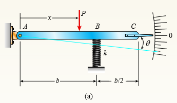
The device shown in the figure consists of a prismatic rigid pointer ABC supported by a uniform translational spring of stiffness k = 950 N/m. The spring is positioned at distance b = 165 mm from the pinned end A of the pointer. The device is adjusted so that, when there is no load P, the pointer reads zero on the angular scale.
(a) If the load P = 11 N, at what distance x should the load be placed so that the pointer will read θ = 25° on the scale (see figure part a)?
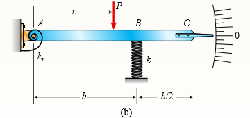
(b) Repeat part (a) if a rotational spring kr = kb2 is added at A (see figure part b).
(c) Let x = 7b/8. What is (N) Pmax if u cannot exceed 28? Include spring kr in your analysis.
(d) Now, if the weight of the pointer ABC is known to be Wp = 3 N and the weight of the spring is Ws = 2.75 N, what initial angular position (i.e., θ in degrees) of the pointer will result in a zero reading on the angular scale once the pointer is released from rest? Assume P = kr = 0.
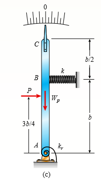
(e) If the pointer is rotated to a vertical position (see figure part c), find the required load P applied at mid-height of the pointer that will result in a pointer reading of θ = 2.5° on the scale. Consider the weight of the pointer Wp in your analysis.
Transcribed Image Text:
A B x- B C b/2 В W. 36/4 k, (с)
> An aluminum pipe has a length of 60 m at a temperature of 10° C. An adjacent steel pipe at the same temperature is 5 mm longer than the aluminum pipe. At what temperature (degrees Celsius) will the aluminum pipe be 15 mm longer than the steel pipe?
> The rails of a railroad track are welded together at their ends (to form continuous rails and thus eliminate the clacking sound of the wheels) when the temperature is 60° F. What compressive stress σ is produced in the rails when they are heated by the s
> A two-story building has steel columns AB in the first floor and BC in the second floor, as shown in the figure. The roof load P1 equals 400 kN, and the second-floor load P2 equals 720 kN. Each column has a length L = 3.75 m. The cross-sectional areas of
> Solve the preceding problem if the axial stress in the middle region is 24,000 psi, the length is 30 in., and the modulus of elasticity is 30 × 106 psi. In part (c), assume that δmax = 0.02 in. Data from Problem 8: A rectangu
> A rectangular bar of length L has a slot in the middle half of its length (see figure). The bar has width b, thickness t, and modulus of elasticity E. The slot has width b/4. (a) Obtain a formula for the elongation δ of the bar due to the ax
> Repeat Problem 5, but now include the weight of the bar. See Table 1 in Appendix I for the weight density of steel. Data from Problem 5: A vertical bar is loaded with axial loads at points B, C, and D, as shown in the figure. The bar is made of steel w
> Repeat Problem 4, but now include the weight of the bar. See Table 1 in Appendix I for the weight density of steel. Data from Problem 4: A vertical bar consists of three prismatic segments A1, A2, and A3 with cross-sectional areas of 6000 mm2, 5000 mm2
> A vertical bar is loaded with axial loads at points B, C, and D, as shown in the figure. The bar is made of steel with a modulus of elasticity E = 29,000 ksi. The bar has a cross-sectional area of 8.24 in2. Calculate the displacements at points B, C, and
> A vertical bar consists of three prismatic segments A1, A2, and A3 with cross-sectional areas of 6000 mm2, 5000 mm2, and 4000 mm2, respectively. The bar is made of steel with E = 200 GPa. Calculate the displacements at points B, D, and E. Ignore the weig
> An aluminum bar AD (see figure) has a cross-sectional area of 0.40 in2 and is loaded by forces p1 = 1700 lb, p2 = 1200 lb, and p3 = 1300 lb. The lengths of the segments of the bar are a = 60 in, b = 24 in, and c = 36 in. (a) Assuming that the modulus of
> A welded steel girder having the cross section shown in the figure is fabricated of two 300 mm × 25 mm flange plates and a 800 mm × 16 mm web plate. The plates are joined by four fillet welds that run continuously for the length
> A long, rectangular copper bar under a tensile load P hangs from a pin that is supported by two steel posts (see figure). The copper bar has a length of 2.0 m, a cross-sectional area of 4800 mm2, and a modulus of elasticity Ec = 120 GPa. Each steel post
> The length of the end segments of the bar (see figure) is 20 in. and the length of the prismatic middle segment is 50 in. Also, the diameters at cross sections A, B, C, and D are 0.5, 1.0, 1.0, and 0.5 in., respectively, and the modulus of elasticity is
> Solve the preceding problem for the following data: b = 8.0 in., k = 16 lb/in., a = 458, and P = 10 lb. Data from Problem 20: A framework ABC consists of two rigid bars AB and BC, each having a length b (see the first part of the figure part a). The ba
> A framework ABC consists of two rigid bars AB and BC, each having a length b (see the first part of the figure part a). The bars have pin connections at A, B, and C and are joined by a spring of stiffness k. The spring is attached at the midpoints of the
> Two pipe columns (AB, FC) are pin- connected to a rigid beam (BCD), as shown in the figure. Each pipe column has a modulus of E, but heights (L1 or L2) and outer diameters (d1 or d2) are different for each column. Assume the inner diameter of each column
> The horizontal rigid beam ABCD is supported by vertical bars BE and CF and is loaded by vertical forces P1 = 400 kN and P2 = 360 kN acting at points A and D, respectively (see figure). Bars BE and CF are made of steel (E = 200 GPa) and have cross-section
> A hollow, circular, cast-iron pipe (Ec = 12,000 ksi) supports a brass rod (Eb = 1 4,000 ksi) and weight W = 2 kips, as shown. The outside diameter of the pipe is dc = 6 in. (a) If the allowable compressive stress in the pipe is 5000 psi and the allowable
> A uniform bar AB of weight W = 25 N is supported by two springs, as shown in the figure. The spring on the left has a stiffness k1 = 300 N/m and natural length L1 = 250 mm. The corresponding quantities for the spring on the right are k2 = 400 N/m and L2
> An aluminum wire having a diameter d = 1/10 in and length L = 12 ft is subjected to a tensile load P (see figure). The aluminum has a modulus of elasticity E = 10,600 ksi If the maximum permissible elongation of the wire is 1/8 in. and the allowable stre
> The three-bar truss ABC shown in the figure part a has a span L = 3 m and is constructed of steel pipes having a cross-sectional area A = 3900 mm2 and modulus of elasticity E = 200 GPa. Identical loads P act both vertically and horizontally at joint C, a
> A short length of a C 200 × 17.1 channel is subjected to an axial compressive force P that has its line of action through the midpoint of the web of the channel (see figure part a). (a) Determine the equation of the neutral axis under this l
> Two rigid bars are connected to each other by two linearly elastic springs. Before loads are applied, the lengths of the springs are such that the bars are parallel and the springs are without stress. (a) Derive a formula for the displacement Î&acu
> A small lab scale has a rigid L-shaped frame ABC consisting of a horizontal arm AB (length b = 30 cm) and a vertical arm BC (length c = 20 cm) pivoted at point B. The pivot is attached to the outer frame BCD that stands on a laboratory bench. The positio
> A small lab scale has a rigid L-shaped frame ABC consisting of a horizontal arm AB (length b = 10 in.) and a vertical arm BC (length c = 7 in.) pivoted at point B. The pivot is attached to the outer frame BCD that stands on a laboratory bench. TheÂ
> A compression bar having a square cross section with sides 50 b 5 mm is subjected to load P. The bar is constructed from two pieces of wood that are connected by a glued joint along plane pq that is inclined at angle α = 35°. The
> Plastic bar AB of rectangular cross section (b = 0.75 in. and h = 1.5 in.) and length L = 2 ft is fixed at A and has a spring support (k = 18 kips/in.) at C (see figure). Initially, the bar and spring have no stress. When the temperature of the bar is ra
> A tension member is to be constructed of two pieces of plastic glued along plane pq (see figure). For purposes of cutting and gluing, the angle u must be between 25° and 45°. The allowable stresses on the glued joint in tension and
> The normal stress on plane pq of a prismatic bar in tension (see figure) is found to be 7500 psi. On plane rs, which makes an angle β = 30° with plane pq, the stress is found to be 2500 psi. Determine the maximum normal stress &Ium
> A prismatic bar is subjected to an axial force that produces a tensile stress σU = 65 MPa and a shear stress τU = 23 MPa on a certain inclined plane (see figure). Determine the stresses acting on all faces of a stress element orient
> Acting on the sides of a stress element cut from a bar in uniaxial stress are tensile stresses of 10,000 psi and 5000 psi, as shown in the figure. (a) Determine the angle u and the shear stress Ï„u, and show all stresses on a sketch of the elem
> Two boards are joined by gluing along a scarf joint, as shown in the figure. For purposes of cutting and gluing, the angle a between the plane of the joint and the faces of the boards must be between 10° and 40°. Under a tensile loa
> A tension member constructed of an L4 × 4 × 1 2 inch angle section is subjected to a tensile load P = 12.5 kips that acts through the point where the mid-lines of the legs intersect (see figure part a). (a) Determine the maxim
> A circular brass bar with a diameter d is member AC in truss ABC that has load P = 5000 lb applied at joint C. Bar AC is composed of two segments brazed together on a plane pq, making an angle α = 36° with the axis of the bar (se
> A copper bar of rectangular cross section (b = 18 mm and h = 40 mm) is held snugly (but without any initial stress) between rigid supports (see figure). The allowable stresses on the inclined plane pq at mids pan, for which θ = 55°
> A plastic bar of rectangular cross section (b = 1.5 in. and h = 3 in.) fits snugly between rigid supports at room temperature (68°F) but with no initial stress (see figure). When the temperature of the bar is raised to 160° F, the c
> A plastic bar of diameter d = 32 mm is compressed in a testing device by a force P = 190 N that is applied as shown in the figure. (a) Determine the normal and shear stresses acting on all faces of stress elements oriented at (1) an angle θ
> The plane truss in the figure is assembled from steel C 10 × 20 shapes. Assume that L = 10 ft and b = 0.71 L. (a) If load variable P = 49 kips, what is the maximum shear stress τmax in each truss member? (b) What is the maximum pe
> A prismatic bar with a length L = 1 m and cross-sectional area A = 1200mm2 is supported at the ends. The bar is then subjected to a temperature increase of ∆T = 25° C. Calculate the complete state of stress acting on an incli
> A prismatic bar with a length L = 3 ft and cross-sectional area A = 8 in2 is compressed by an axial centroidal load P = 10 kips. Determine the complete state of stress acting on an inclined section pq that is cut through the bar at an angle θ
> A copper bar with a rectangular cross section is held without stress between rigid supports (see figure). Subsequently, the temperature of the bar is raised 50° C. (a) Determine the stresses on all faces of the elements A and B, and show these
> During a tension test of a mild-steel specimen (see figure), the extensometer shows an elongation of 0.00120 in. with a gage length of 2 in. Assume that the steel is stressed below the proportional limit and that the modulus of elasticity E = 30 Ã
> A steel bar with a diameter d = 12 mm is subjected to a tensile load P = 9.5 kN (see figure). (a) What is the maximum normal stress σmax in the bar? (b) What is the maximum shear stress τmax? (c) Draw a stress element oriented at 45
> A short column with a wide-flange shape is subjected to a compressive load that produces a resultant force P = 55 kN acting at the midpoint of one flange (see figure). (a) Determine the maximum tensile and compressive stresses σt and Ï
> A brass wire of diameter d = 1/16 in. is stretched between rigid supports with an initial tension T of 37 lb (see figure). Assume that the coefficient of thermal expansion is 10.6 × 10⁻⁶/°F and the modulus of elasticity is 15 × 106 psi. (a) If the temper
> A brass wire of diameter d = 2.42 mm is stretched tightly between rigid supports so that the tensile force is T = 98 N (see figure). The coefficient of thermal expansion for the wire is 19.5 × 10⁻⁶/°C, and the modulus of elasticit
> A standard brick (dimensions 8 in. × 4 in. × 2.5 in.) is compressed lengthwise by a force P, as shown in the figure. If the ultimate shear stress for brick is 1200 psi and the ultimate compressive stress is 3600 psi, what force
> A circular steel rod of diameter d is subjected to a tensile force P = 3.5 kN (see figure). The allowable stresses in tension and shear are 118 MPa and 48 MPa, respectively. What is the minimum permissible diameter dmin of the rod? P P = 3.5 kN
> A steel bar of rectangular cross section (1.5 in. × 2.0 in.) carries a tensile load P (see figure). The allowable stresses in tension and shear are 14,500 psi and 7,100 psi, respectively. Determine the maximum permissible load Pmax. 2.0
> A safety valve on the top of a tank containing steam under pressure p has a discharge hole of diameter d (see figure). The valve is designed to release the steam when the pressure reaches the value pmax. If the natural length of the spring is L and its s
> A device consists of a horizontal beam ABC supported by two vertical bars BD and CE. Bar CE is pinned at both ends but bar BD is fixed to the foundation at its lower end. The distance from A to B is 600 mm and from B to C is 350 mm. Bars BD and CE have l
> Rigid bar ACB is supported by an elastic circular strut DC having an outer diameter of 15 in. and inner diameter of 14.4 in. The strut is made of steel with a modulus elasticity of E = 29,000 ksi. Point load P = 5 kips is applied at B. Calculate the chan
> By what distance h does the cage shown in the figure move downward when the weight W is placed inside it? (See the figure.) Consider only the effects of the stretching of the cable, which has axial rigidity EA = 10,700 kN. The pulley at A has a diameter
> A short column constructed of a W12 × 35 wide-flange shape is subjected to a resultant compressive load P = 25 k having its line of action at the midpoint of one flange (see figure). (a) Determine the maximum tensile and compressive stresses
> A steel wire and an aluminum alloy wire have equal lengths and support equal loads P (see figure). The moduli of elasticity for the steel and aluminum alloy are Es = 30,000 ksi and Ea = 11,000 ksi, respectively. (a) If the wires have the same diameters,
> A steel cable with a nominal diameter of 25 mm is used in a construction yard to lift a bridge section weighing 38 kN, as shown in the figure. The cable has an effective modulus of elasticity E = 140 GPa. (a) If the cable is 14 m long, how much will it s
> The L-shaped arm ABCD shown in the figure lies in a vertical plane and pivots about a horizontal pin at A. The arm has a constant cross-sectional area and total weight W. A vertical spring of stiffness k supports the arm at point B. (a) Obtain a formula
> Rigid bar ABC is supported with a pin at A and an elastic steel rod at C. The elastic rod has a diameter of 25 mm and modulus of elasticity E = 200 GPa. The bar is subjected to a uniform load q on span AC and a point load at B. Calculate the change in le
> A 10-ft rigid bar AB is supported with a vertical translational spring at A and a pin at B. The bar is subjected to a linearly varying distributed load with maximum intensity qo. Calculate the vertical deformation of the spring if the spring constant is
> Find expressions for all support reaction forces in the plane frame with load 3P applied at C as shown in the figure. Joints A and D are pin supported, and there is a roller support at joint F. The lengths and the properties of the members are shown in t
> A trimetallic bar is uniformly compressed by an axial force P = 9 kips applied through a rigid end plate (see figure). The bar consists of a circular steel core surrounded by brass and copper tubes. The steel core has a diameter of 1.25 in., the brass tu
> Find expressions for all support reaction forces in the plane frame with load 2P applied at C, as shown in the figure. Joint A is a sliding support, joint D is pinned, and joint F is a roller support. Assume that member AC is a flat prismatic bar of leng
> A rigid bar AB of a length L = 66 in is hinged to a support at A and supported by two vertical wires attached at points C and D (see figure). Both wires have the same cross-sectional area (A = 0 .0272 in2 ) and are made of the same material (modulus E =
> A rigid bar ABCD is pinned at point B and supported by springs at A and D (see figure). The springs at A and D have stiffnesses k1 = 10 kN/m and k2 = 25 kN/m, respectively, and the dimensions a, b, and c are 250 mm, 500 mm, and 200 mm, respectively. A lo
> A bar AB supports a load P acting at the centroid of the end cross section (see figure). In the middle region of the bar the cross-sectional area is reduced by removing one-half of the bar. (a) If the end cross sections of the bar are square with sides o
> A horizontal rigid bar of weight W = 7200 lb is supported by three slender circular rods that are equally spaced (see figure). The two outer rods are made of aluminum (E1 = 10 × 106 psi)with diameter d1 = 0.4 in and length L1 = 40 in. The in
> Three-bar truss ABC (see figure) is constructed of steel pipes having a cross-sectional area A = 3500 mm2 and a modulus of elasticity E = 210 GPa. Member BC is of length L = 2.5 m, and the angle between members AC and AB is known to be 60°. Me
> A bimetallic bar (or composite bar) of square cross section with dimensions 2b × 2b is constructed of two different metals having moduli of elasticity E1 and E2 (see figure). The two parts of the bar have the same cross-sectional dimensions.
> A rigid bar of weight W = 800 N hangs from three equally spaced vertical wires (length L = 150 mm, spacing a = 50 mm): two of steel and one of aluminum. The wires also support a load P acting on the bar. The diameter of the steel wires is ds = 2 mm, and
> The aluminum and steel pipes shown in the figure are fastened to rigid supports at ends A and B and to a rigid plate C at their junction. The aluminum pipe is twice as long as the steel pipe. Two equal and symmetrically placed loads P act on the plate at
> A hollow circular pipe (see figure) supports a load P that is uniformly distributed around a cap plate at the top of the lower pipe. The inner and outer diameters of the upper and lower parts of the pipe are d1 = 50 mm, d2 = 60 mm, d3 = 57 mm, and d4 = 6
> A bungee cord that behaves linearly elastically has an unstressed length Lo = 760 mm and a stiffness k = 140 N/m. The cord is attached to two pegs, distance b = 380 mm apart, and is pulled at its midpoint by a force P = 80 N (see figure). (a) How much st
> A block B is pushed against three springs by a force P (see figure). The middle spring has a stiffness k1, and the outer springs each have stiffness k2. Initially, the springs are unstressed, and the middle spring is longer than the outer springs (the di
> A compressive load P is transmitted through a rigid plate to three magnesium-alloy bars that are identical except that initially the middle bar is slightly shorter than the other bars (see figure). The dimensions and properties of the assembly are as fol
> A slightly tapered bar AB of rectangular cross section and length L is acted upon by a force P (see figure). The width of the bar varies uniformly from b2 at end A to b1 at end B. The thickness t is constant. (a) Determine the strain energy U of the bar.
> Two cables, each carrying a tensile force P = 1200 lb, are bolted to a block of steel (see figure). The block has thickness t = 1 in and width b = 3 in. (a) If the diameter d of the cable is 0.25 in., what are the maximum tensile and compressive stresses
> The statically indeterminate structure shown in the figure consists of a horizontal rigid bar AB supported by five equally spaced springs. Springs 1, 2, and 3 have stiffnesses 3k, 1.5k, and k, respectively. When unstressed, the lower ends of all five spr
> The truss ABC shown in the figure supports a horizontal load P1 = 300 lb and a vertical load P2 = 900 lb. Both bars have a cross-sectional area A = 2.4 in2 and are made of steel with E = 30 × 106 psi. (a) Determine the strain energy U1 of th
> The truss ABC shown in the figure is subjected to a horizontal load P at joint B. The two bars are identical with cross-sectional area A and modulus of elasticity E. (a) Determine the strain energy U of the truss if the angle β = 60Â&de
> Determine the strain energy per unit volume (units of psi) and the strain energy per unit weight (units of in.) that can be stored in each of the materials listed in the accompanying table, assuming that the material is stressed to the proportional limit
> The bar ABC shown in the figure is loaded by a force P acting at end C and by a force Q acting at the midpoint B. The bar has a constant axial rigidity EA. (a) Determine the strain energy U1 of the bar when the force P acts alone (Q = 0). (b) Determine t
> A three-story steel column in a building supports roof and floor loads as shown in the figure. The story height H is 10.5 ft, the cross-sectional area A of the column is 15.5 in2, and the modulus of elasticity E of the steel is 30 × 106 psi.
> A bar with a circular cross section having two different diameters d and 2d is shown in the figure. The length of each segment of the bar is L/2, and the modulus of elasticity of the material is E. (a) Obtain a formula for the strain energy U of the bar
> A prismatic bar AD of length L, cross- sectional area A, and modulus of elasticity E is subjected to loads 5P, 3P, and P acting at points B, C, and D, respectively (see figure). Segments AB, BC, and CD have lengths L/6, L/2, and L/3, respectively. (a) Ob
> A tube structure is acted on by loads at B and D, as shown in the figure. The tubes are joined using two flange plates at C that are bolted together using six 0.5-in. diameter bolts. (a) Derive formulas for the reactions RA and RE at the ends of the bar.
> The fixed-end bar ABCD consists of three prismatic segments, as shown in the figure. The end segments have a cross-sectional area A1 = 840 mm2 and length L1 = 200 mm. The middle segment has a cross-sectional area A2 = 1260 mm2 and length L2 = 250 mm. Loa
> A circular post, a rectangular post, and a post of cruciform cross section are each compressed by loads that produce a resultant force P acting at the edge of the cross section (see figure). The diameter of the circular post and the depths of the rectang
> A prismatic bar with a diameter do = 20 mm is being compared with a stepped bar of the same diameter (d1 = 2 0mm) that is enlarged in the middle region to a diameter d2 = 25 mm (see figure). The radius of the fillets in the stepped bar is 2.0 mm. (a) Doe
> Three steel cables jointly support a load of 12 kips (see figure). The diameter of the middle cable is 3/4 in. and the diameter of each outer cable is 1/2 in. The tensions in the cables are adjusted so that each cable carries one-third of the load (i.e.,
> A plastic rod AB of length L = 0.5 m has a diameter d1 = 30 mm (see figure). A plastic sleeve CD of length c = 0.3 m and outer diameter d2 = 45 mm is securely bonded to the rod so that no slippage can occur between the rod and the sleeve. The rod is made
> Repeat Problem 8, but assume that the bar is made of aluminum alloy and that BC is prismatic. Assume that P = 20 kips, L = 3 ft, t = 1/4 in, b1 = 2 in, b2 = 2.5 in., and E = 10,400 ksi. Data from Problem 8: Bar ABC is fixed at both ends (see figure) a
> Bar ABC is fixed at both ends (see figure) and has load P applied at B. Find reactions at A and C and displacement δB if P = 200 kN, L = 2 m, t = 20 mm, b1 = 100 mm, b2 = 115 mm, and E = 96 GPa. b2 3L/5 2L/5 B P A C
> Three prismatic bars, two of material A and one of material B, transmit a tensile load P (see figure). The two outer bars (material A) are identical. The cross-sectional area of the middle bar (material B) is 50% larger than the cross-sectional area of o
> A solid circular steel cylinder S is encased in a hollow circular aluminum tube A. The cylinder and tube are compressed between the rigid plates of a testing machine which applies forces P. Calculate the allowable value of the compressive force if the yi
> A horizontal rigid bar ABC is pinned at end A and supported by two cables at points B and C. A vertical load P = 10 kN acts at end C of the bar. The two cables are made of steel with a modulus elasticity E = 200 GPa and have the same cross- sectional are
> A steel bar with a uniform cross section is fixed at both ends. A load P = 2.5 kips is applied at point C. The bar has a cross-sectional area of 8 in2. Calculate the reactions at joints A and B and the displacement at joint C. Assume that the modulus of
> A cylindrical assembly consisting of a brass core and an aluminum collar is compressed by a load P (see figure). The length of the aluminum collar and brass core is 350 mm, the diameter of the core is 25 mm, and the outside diameter of the collar is 40 m
> A plain concrete wall (i.e., a wall with no steel reinforcement) rests on a secure foundation and serves as a small dam on a creek (see figure). The height of the wall is h = 6.0 ft and the thickness of the wall is t = 1.0 ft. (a) Determine the maximum t
> The assembly shown in the figure consists of a brass core (diameter d1 = 0.25 in) surrounded by a steel shell (inner diameter d2 = 0.28 in, outer diameter d3 = 0.35 in). A load P compresses the core and shell that both have a length L = 4.0 in. The modul
> Repeat Problem 29 if vertical load P at D is replaced by a horizontal load P at D (see figure). Data from Problem 29: A T-frame structure is composed of prismatic beam ABC and non prismatic column DBF that are joined at B by a frictionless pin connect

